


Keysight 85309B User’s and Service Guide 2-7
Operating Information
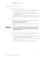
85309B Rear Panel Features
J4 REFERENCE IF IN. This port receives the IF from the reference mixer. The
85309B amplifies this signal and sends it to the receiver using the J10
REFERENCE IF OUT connector.
J5 REFERENCE DET IN. A power detector in the reference mixer measures
incoming LO power and outputs a proportional voltage. This voltage enters the
85309B through this connector, and is used to level the LO power. The
allowable input voltage range for this connector is 0 to -200 mV.
Test Mixers Connector Group
The three Type-N female connectors in this group, J3 TEST 1 LO/IF (standard),
J11 TEST 2 LO/IF (option 001 or 401), and J13 TEST 3 LO/IF (option 002 or
402), are connected to the test mixers. A test mixer only requires one
connection. A diplexer allows the LO signal (which goes to the test mixer) and
the IF signal (which comes back from the test mixer) to travel over the same
physical cable. This allows both signals to go through a single-channel rotary
joint.
J3 TEST 1 LO/IF (standard). This port sends the local oscillator signal to the
test mixer, and receives the IF signal over the same connection. A diplexer
inside the test mixer and the 85309B makes this possible.
The IF signal from the test mixer is amplified and sent to the receiver through
J9 TEST 1 IF OUT.
J11 TEST 2 LO/IF (option 001). This port operates the same as the TEST 1
LO/IF port. Option 001 or 401 adds a second test channel.
The IF signal from a second test mixer is amplified and sent to the receiver
through J12 TEST 2 IF OUT.
J13 TEST 3 LO/IF (option 002). This port operates the same as the TEST 1
LO/IF and TEST 2 LO/IF ports. Options 002 or 402 adds a third test channel.
The IF signal from a third test mixer is amplified and sent to the receiver
through J14 TEST 3 IF OUT.
LO Source Connector Group
The two Type-N female connectors in this group, J1 LO INPUT and J6 POS Z
BLANK, are connected to the LO source.
J1 LO INPUT. Receives the local oscillator signal from the LO source. The
85309B distributes this to the test and reference mixers.
J6 POS Z BLANK. The LO source sends out the POS Z BLANK (TTL logic) signal
during sweep retrace. POS Z BLANK is monitored by the 85309B through this
connector. The 85309B monitors this signal, and lowers the gain in the
automatic leveling control circuit during retrace. This keeps the gain of the ALC
from peaking during known power drops.
Содержание 85309B LO/IF
Страница 6: ...vi Keysight 85309B User s and Service Guide...
Страница 18: ...1 10 Keysight 85309B User s and Service Guide Getting Started Getting Help with Your 85309B 1...
Страница 44: ...2 26 Keysight 85309B User s and Service Guide Operating Information Performing the Operator s Check 2...
Страница 59: ...Keysight 85309B User s and Service Guide 4 5 Service Replaceable Parts Figure 4 2 Cable Locations Standard...
Страница 63: ...Keysight 85309B User s and Service Guide 4 9 Service Replaceable Parts Figure 4 4 Cable Locations Option 001...
Страница 68: ...4 14 Keysight 85309B User s and Service Guide Service Replaceable Parts 4 Figure 4 6 Cable Locations Option 002...
Страница 73: ...Keysight 85309B User s and Service Guide 4 19 Service Replaceable Parts Figure 4 8 Cable Locations Option 400...
Страница 79: ...Keysight 85309B User s and Service Guide 4 25 Service Replaceable Parts Figure 4 10 Cable Locations Option 401...
Страница 85: ...Keysight 85309B User s and Service Guide 4 31 Service Replaceable Parts Figure 4 12 Cable Locations Option 402...
Страница 86: ...4 32 Keysight 85309B User s and Service Guide Service Replaceable Parts 4...
Страница 87: ...Installation Note Xxxxx xxxxx 3...


