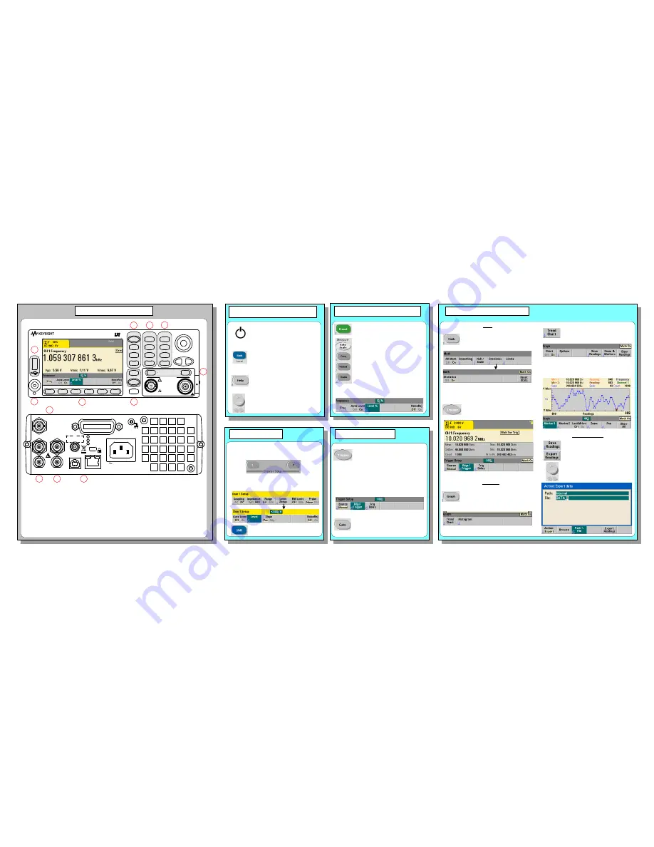
3. Channel Selection
4. Triggering and Gating
1. Power-On, Local Control, Built-In
Help, Alphanumeric Entry
A Counter Measurements
(Chapter 3)
B Display Control
(Chapter 6)
C Instrument Wide
(Chapter 1)
D Channel Configuration
(Chapter 4)
E Triggering and Gating
(Chapter 5)
F Soft Key Area
(all chapters)
G On / Standby
(Chapter 1)
H
USB “Host” Port
(Chapter 7)
Panels at a Glance
Front Panel Features
A
B
C
E
F
H
D
G
I
J
K
L
Rear Panel Features
I Parallel Rear Panel Inputs
(Chapter 4)
J Remote Interface (USB, LAN)
(Chapter 2)
K External Triggering and Gating
(Chapter 5)
L Frequency Reference
(Chapter 3)
5. Math, Graphics, Reading Storage
Turns the counter on and off (standby).
A self-test and auto-cal occurs during
the power-on sequence and the
counter is set to its preset settings.
Transfers instrument control from the
remote interface (LAN, USB, GPIB) to
the front panel. Also displays the
previous softkey menu.
Displays help topics which can be
selected using the rotary knob. Press
and hold any function key or softkey
to display help for that key or feature.
Use the rotary knob and arrows to cycle
through and enter alphanumeric char-
acters and to navigate through files and
folders when browsing the file system.
Place the counter in a known state
before selecting the measurement.
Select a measurement function by
pressing the corresponding key
within the ‘Measure’ column. Select a
specific measurement using the
softkeys below the display.
Use Auto Scale (signals > 100 Hz) to
automatically detect the input signal
and set the range and trigger thres-
hold.
2. Setting the Measurement Function
Use the channel number keys to select the
active input channel and display the channel
configuration softkeys:
Example (Ch.1): - DC coupling
- 50
W
impedance
- 2.0V trigger threshold
Use the ‘Trigger’ key to select the
trigger configuration softkeys (source,
readings per trigger, delay), or to issue
a manual trigger.
Example: -
trigger source ‘Manual’
(
‘Trigger’ key)
- 1000 readings per trigger
(use shifted numeric keys)
Tip
: numeric values can also be entered
using the “shifted” numeric keys.
Use the ‘Gate’ key and gate softkeys
to specify gate time, gate delay, and
other gate parameters.
Use the ‘Math’ key to view the math
functions available through the
softkeys.
‘All Math’ plus the selected
function must be
On
.
Example: - compute statistics of 1,000
readings.
Press the ‘Trigger’ key to send a single
trigger and start the measurements
(Steps 2-4).
Use the ‘Graph’ and related softkeys to
select a trend chart or enable a
histogram for graphical representations
of the measurements.
Example: - trend chart of 1,000 readings
- view last 100 readings
- open Zoom & Markers menu
Use the ‘Trend Chart’ softkey to view a
chart of the readings taken, or currently
being taken.
Use the ‘Save Readings’ and ‘Export
Readings’ softkeys within the trend
chart or histogram menus to save data
internally or to an external USB device.
Use the front panel knob and arrows to
create file names and browse through
the file system.
Math
Graphics
Reading Storage
User’s Guide
User’s Guide
Front and rear panels shown with product Option
106/115 (Channel 2) and Option 400 (GPIB).
Internal triggering automatically
starts the measurements.
Preset
Digits
Help
Utility
Shift
Graph
3
6
7
1
4
2
5
0
9
8
+/-
.
Math
Data
Log
Auto
Scale
Freq
Period
Ratio
Measure
View
System
Trigger
Gate
Back
Local
53210A
350 MHz
RF Counter
1
2
Channel / Setup
!
1 Watt Max into 50
W
Opt 010 UOCXO
Line
100-240V, 50-60 Hz
100-127V, 400 Hz
90VA Max
USB LAN
Int Ref Out Trig In
Ext Ref In Gate In/Out
Opt 106/115
Opt 300 Battery
Ch 1 Opt 201 Ch 2
(53220A/53230A Only)
GP-IB
Opt 150 sw
(53230A Only)


