


L
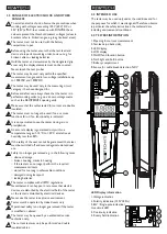
CD Display information
1. HOLD symbols
2. AC/ DC and polarity symbols
3. Function symbols (from left to right, upper row: voltage
test, current test, low voltage test, resistance test; lower
row: diode test, frequency test, cable break detected by
NCV, continuity test).
4. Low battery indication
5. 4 digit 7 segment display
6.0 PREPARATION FOR TESTS
6.1 Auto-power-on/ switching on
• The tester switches on when it detects shorten tips, or
an AC or DC voltage above approx. 6 V or a live phase
on L2+ (single pole test).
• It can be switched on with a button.
6.2. Auto-power off
• Tester is automatically powered off after approx.
10 sec when there is no signal contacted to the probes.
• The torch light automatically switches off after approx.
30 sec.
7.0 CONDUCTING TESTS
7.1 Voltage test
• Connect both probes to the object under test.
• The voltage is indicated by LEDs if >120 V.
• The buzzer and vibration function turn on if the voltage
is higher than 50 V AC or 120 V DC.
• Voltage polarity is indicated in following manner on the
LCD.
AC: AC symbol is on
+DC: DC symbol is on
-DC: - symbol and DC symbol is on
• Above 120 V, the polarity is shown on the LED display
as well.
AC: both 120 V LEDs are on
+DC: left 120 V LED is on
-DC: right 120 V LED is on
• Once the tester is powered on, it will automatically
measure voltage in range 6V-1000VAC/1500VDC.
When the L2 probe + is the positive (negative)
potential, the Polarity indication LED indicates
“+DC” (“-DC”).
During voltage test, L or R LED/Symbol may light up.
In case of empty batteries, only the ELV LED lights up
>50 V.
1
2
3
4
5
7.1.1 Low Voltage mode – 1V-1000VAC/1500VDC
• Press On/Off/Function button repeatedly until the
LCD shows <10V symbol.
• In Low Voltage mode it is possible to measure AC and
DC voltage from 1V.
• Connect both probes to the object under test.
• Voltage display is as in 7.1 described.
Continuity mode is disabled in Low Voltage Mode.
7.2 CURRENT TEST
• Press On/off/ Function button repeated until LCD
shows A symbol.
• In current test mode, currents between 0.1 A and
200 A can be tested.
• The cable under test needs to be positioned in the
centre of the opening and adjacent to the two markings
on either side of the the moulding.
• Make sure that only double insulated cables are
measured.
• Store test probes safely to avoid any unintended
connection.
• The tester will automatically switch to voltage
measurement if a voltage is detected >6 V.
7.3 SINGLE-POLE PHASE TEST
Function of this test may not be fully achieved if
the insulation condition / grounding conditions of
user or of the equipment under test are not good
enough. Verification of live-circuit should not be
dependent on this Single-pole phase test only, but
on the voltage test (as in 7.1).
• Hold the tester firmly in your hand. Connect the “L2
+” probe to the object under test. Live circuit LED
lights up and the buzzer sounds when a voltage of
approx. 100 V AC or more exists in the object under
test. (Pol
≥
100 V AC).
• Indication of Single Pole phase test is via LED.
7.4 PHASE ROTATION TEST
• L LED (symbol) and R LED (symbol) for Phase rotation
test may operate on various wiring systems, but
effective testing result can be obtained only on a three-
phase 4-wire system.
• Hold the tester firmly in your hand and connect both
probes to the object under test.
• Phase-to-phase voltage is indicated by Voltage LEDs
and LCD.
• R LED lights up for Right rotary field.
• L LED lights up for Left rotary field.
• Measurement principle: The instrument detects the
phase rising order regarding the user as earth.
Function of this test may not be fully achieved if the
insulation condition/ grounding conditions of the
user or of the equipment under test is not good
enough.


