

e300i User Manual
Document #: 0503M01A
REV : 1.3
Approval:
Date: March ’08
Page 12 of 25
4 SITE CONSIDERATIONS AND MOUNTING
4 SITE CONSIDERATIONS AND MOUNTING
4 SITE CONSIDERATIONS AND MOUNTING
4 SITE CONSIDERATIONS AND MOUNTING
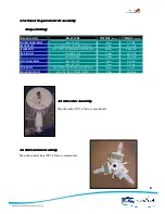
The turbine is supplied with a “weld on” mounting flange for adaptation. Custom structures must
incorporate a 76mm (3”) - 100mm (4”) diameter pipe for machine mounting. Larger pipes may
interfere with the blades when pitch control operates.
There are infinite variations on sites and the information and suggestions may be adapted to suit
local conditions. Wind speed increases with height above the ground. An installation site should be
chosen which is free of obstructions like buildings, trees, mounds and hills. A "pure" airflow is
paramount for good performance. Naturally some compromise can be reached but there should
be a clear entry for the prevailing wind direction of the location. The absolute minimum height of
the structure should be 9m when placed clear of obstructions.
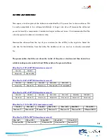
The general rule is that the e300
iiii
should be 8m (25’) higher than any obstruction within a 150m
(500’) radius of the tower. Otherwise mount the e300
iiii
as high as possible. All obstructions add to
possible turbulence, which will cause undue stress on the unit and reduced performance. Wind
speed increases with height above the ground. The power in the wind is a cubic function of wind
speed. Doubling the wind speed increases the power by eight times.
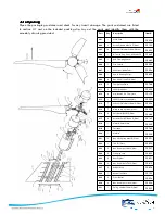
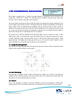
4.1 Flange Mounting Detail
4.1 Flange Mounting Detail
4.1 Flange Mounting Detail
4.1 Flange Mounting Detail
The e300
iiii
is mounted using eight M8 Hi-Tensile bolts and spring washers fitted through the bottom
flange on the weather cocking swivel assembly.
4.2
4.2
4.2
4.2 Roof Mounting
Roof Mounting
Roof Mounting
Roof Mounting
Roof mounting is possible but the turbine performance may suffer as a result of wind shift and
turbulence. Roof mounting structures are beyond the scope of this document and must comply with
the relevant structural standards that are in force.
4.
4.
4.
4.3
3
3
3 Towers
Towers
Towers
Towers
Towers are required to conform to relevant standards and must be designed to withstand the
loading regime of the wind turbine. Full details are included with any Kestrel tower kit supplied.
12
4
4
S
S
i
i
t
t
e
e
C
C
o
o
n
n
s
s
i
i
d
d
e
e
r
r
a
a
t
t
i
i
o
o
n
n
s
s
a
a
n
n
d
d
M
M
o
o
u
u
n
n
t
t
i
i
n
n
g
g
4
4
.
.
1
1
F
F
l
l
a
a
n
n
g
g
e
e
M
M
o
o
u
u
n
n
t
t
i
i
n
n
g
g
D
D
e
e
t
t
a
a
i
i
l
l
4
4
.
.
2
2
R
R
o
o
o
o
f
f
M
M
o
o
u
u
n
n
t
t
i
i
n
n
g
g
4
4
.
.
3
3
T
T
o
o
w
w
e
e
r
r
s
s


