


K4C COMPACT-MULTI – INSTALLATION/OPERATION MANUAL
K4C Compact-multi
Feb
-06
8
3.10 BLOWER SETTING
Ensure power is off when adjusting blower setting
. For heating, use the blower
speeds shown on the furnace specifications to give a rise of 70 - 85°F. The #4 Lo
blower speed can be used for air circulation when neither heating nor cooling are
required. Set blower speeds to match the installation requirements. AC models include
a fan centre relay wired to run the blower at #1 Hi speed when the cooling cycle is
operating. For normal operation select “AUTO” on the T87F thermostat. When “FAN
ON” is selected the blower runs constantly at the cooling speed. See “OFF CYCLE AIR
CIRCULATION” section.
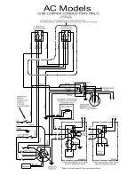
3.11 COOLING – AC MODELS
AC models include a fan centre relay wired to run the blower at #1 Hi speed when the
cooling cycle is operating. For normal operation, select “AUTO” on the T87F
thermostat. When “FAN ON” is selected the blower runs constantly at the cooling
speed. See “OFF CYCLE AIR CIRCULATION”.
Height of the coil above the heat
exchanger shall be no less than 4” (100 mm).
3.12 HUMIDIFIER
If a humidifier is installed ensure that no water can drip or run from it into the furnace.
This would cause deterioration and void the furnace warranty.
3.13 THERMOSTAT ANTICIPATOR SETTING
0.2 amps for any burner. Check that the thermostat anticipator setting matches the
primary control circuit current draw. This setting affects the thermostat’s response to
the control.
3.14 BLOCKED VENT SWITCH
ONLY APPLICABLE TO CANADA
NOT APPLICABLE FOR DIRECT VENT SYSTEMS
SWITCH
The blocked vent switches are flue gas spillage safety devices. They
OPERATION
detect spillage of flue gas products due to a clocked flue system or
inadequate draft. The switch senses the spillage of hot flue gases and
de-energizes the system’s burner control.
NEVER reset the blocked
vent switch, unless the cause of the blockage has been corrected.
INSTALLATION
1. Pierce a 5/8” hole into the flue vent pipe near the appliance breech connection.
2. This hole must be at least 10” before the draft regulator, vertically or horizontally.
3. Remove one of the securing nuts from the threaded tube of the safety switch.
4. Tighten the other securing nut onto the pipe as far as possible.
5. Insert the threaded tube end into the pierced hole of the flue vent pipe.
6. Install the securing nut on the safety switch tube, which protrudes into the flue
vent pipe. Tighten the nut securely.