22
TK-980/981
INSTALLATION
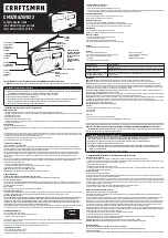
7. PA/HA Unit (KAP-1 : Option)
7-1. Installing the KAP-1 in the Transceiver
The Horn Alert (max. 2A drive) and Public Address func-
tions are enabled by inserting the KAP-1 W1 (3P; white/
black/red) into CN3 on the TX-RX unit (A/2), inserting W2
(3P; green) into CN5 on the TX-RX unit (A/2), and connecting
the KCT-19 (option) to CN2 and CN3 of the KAP-1.
• Installation procedure
1. Open the upper case of the transceiver.
2. Insert the two cables (
1
) with connectors from the
KAP-1 switch unit into the connectors on the transceiver.
3. Secure the switch unit board to the chassis with a
screws (
3
). The notch (
2
) in the board must be
placed at the front left side.
4. Attach the cushion on the top of the KAP-1 switch unit.
2
1
1
3
4
W1
W2
CN1
CN2
CN3
KCT-19
Cushion
(G13-1710-04)
CN3
CN5
Fig. 10
R1
Output form
HR1 (Default)
Yes
HR2
No
HR1
HR1
HR2
• Public address
The signal from pin 13 of IC7 on the TX-RX unit (A/2)
drives PA relay in the KAP-1 and switches the audio power
amplifier output between the external PA system (through
KCT-19) and internal and external speakers.
To use the PA function, R109 on the TX-RX unit (A/2)
must be removed.
R109
Use the PA function
No
Do not use the PA function
Yes
TX-RX UNIT
(A/2)
KCT-19
CN7
PA
R109
ANT
R1
Fig. 11
KAP-1 foil side view
Fig. 12
7-2. Modifying the Transceiver
• Horn alert
The signal from pin 4 of IC7 on the TX-RX unit (A/2) turns
Q4 and Q6 on and off and drives KAP-1 HA relay to drive the
horn with a maximum of 2A.
The default output is HR1. The relay open output can be
obtained between HR1 and HR2 by removing R1 in the KAP-
1.