background image

RXD-655/755

4

DISASSEMBLY FOR REPAIR

Caution on Disassembly

Follow the below-mentioned notes when disassembling
the unit and reassembling it, to keep it safe and ensure
excellent performance:
1. Take cassette tape and compact disc out of the unit.
2. Be sure to remove the power supply plug from the wall

outlet before starting to disassemble the unit.

3. Take off nylon bands or wire holders where they need be

removed when disassembling the unit. After servicing
the unit, be sure to rearrange the leads where they were
before disassembling.

4. Take suffcient care on static electricity of integrated

circuits and other circuits when servicing.

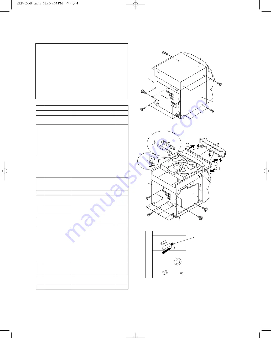
Figure 7-2

Figure 7-3

1

Top Cabinet

1. Screw ..................... (A1) x4

7-1

2

Side Panel

1. Screw ..................... (B1) x8

7-1

(Left/right)

3

CD Player Unit/

1. Turn on the power supply,

7-2

CD Tray Cover

    open the disc tray, take out
    the CD cover, and close.
    (Note 1)
2. Screw ..................... (C1) x1
3. Hook ....................... (C2) x3
4. Hook ....................... (C3) x2
5. Socket .................... (C4) x2

4

Rear Panel

1. Screw ..................... (D1) x9

7-2

5

Main PWB

1. Screw ..................... (E1) x1

7-2

2. Socket .................... (E2) x3

8-2

3. Flat Cable .............. (E3) x1
4. Tip Wire .................. (E4) x1

6

Power Supply PWB 1. Screw ..................... (F1) x2

8-2

2. Socket .................... (F2) x1
3. Flat Wire ................. (F3) x1

8-3

7

Front Panel

1. Screw ..................... (G1) x3

8-2

8

Display PWB

1. Screw ..................... (H1) x9

8-3

2. Socket .................... (H2) x1

9

Tape Mechanism 1. Open the cassette holder.

8-3

2. Screw...................... (J1) x5

10

Headphones PWB 1. Screw ..................... (K1) x1

8-3

11

Turntable

1. Hook ....................... (L1) x2

8-4

2. Cover ..................... (L2) x1

12

Disc Tray

1. Turn fully the lock  lever in the

7-3

arrow direction.

2. While holding the lock lever,rotate

8-1

the cam gear until the cam gear
rib engages with the clamp lever.

3. Push the slide holder backward to

8-5

engage the claw with the groove
and remove it in the direction
of the arrow. .............. (M1) x6

13

CD Servo PWB

1. Screw ..................... (N1) x1

8-6

(Note 2)

2. Hook ....................... (N2) x2
3. Socket .................... (N3) x4

14

CD Mechanism

1. Hook ....................... (P1) x2

9-1

2. Hook ....................... (P2) x3

15

Loading Motor PWB 1. Hook ....................... (Q1) x5

9-1

STEP

REMOVAL

PROCEDURE

FIGURE

Figure 7-1

(B1)x4
ø3x10mm

(B1)x2
ø3x10mm

Rear
Panel

(B1)x2
ø3x10mm

Side Panel
(Right)

Side Panel
(Left)

(A1)x2
ø3x12mm

(A1)x2
ø3x12mm

Top Cabinet

(E1)x1
ø3x10mm

(C3)x1

(D1)x2
ø3x10mm

(C1)x1
ø3x10mm

(D1)x7
ø3x10mm

CD Player
Unit

DC Tray  Cover

Rear
Panel

Pull

(C3) x1

(C4)x2

(C2) x3

1

1

2

Main PWB

CD Servo
PWB

Note 1:

How to open the changer manually. (Fig. 7-3)
1.  In this state, turn fully the lock lever in the arrow direction

through the hole on the loading chassis bottom.

2. While holding the lock lever, rotate the cam gear anticlockwise

until the cam gear rib engages with the clamp lever. (Fig. 8-1)

3.  After that, push forward the CD slide holder.

Note 2:

1. After removing the connector for the optical pickup from the

connector, wrap the conductive aluminium foil around the
front end of the connector so as to protect the optical pickup
from electrostatic damage.

Note 3:

1. Be careful not to break the claw of the CD mechanism.
2. When fining back the cam gear assembly, let it lock by front

movement.

LOCK LEVER

Содержание RXD-655

Страница 1: ... or inside the product relating to laser prod uct safety KENWOOD Crop certifies this equipment conforms to DHHS Regulations No 21 CFR 1040 10 Chapter 1 subchapter J DANGER Laser radiation when open and interlock defeated AVOID DIRECT EXPOSURE TO BEAM Refer to parts list on page 33 Panel CD A60 2090 08 Front glass B10 RXD 655E H 655L 655M 655M H RXD 755 755E 755L 755M SERVICE MANUAL XD 655 855 Refe...

Страница 2: ... product has been classified asClass 1 It means that there isno danger of hazardous radiatio outside t heproduct SYSTEM MAIN UNIT DESTINATION SPEAKER XD 655 RXD 655 ET LS N50S XD 655E RXD 655E E2 LS N50S XD 655 GR RXD 655 GR ET LS N50S GR XD 655E GR RXD 655E GR E2 LS N50S GR XD 655 H RXD 655 H E LS N50S H XD 655E H RXD 655E H E2 LS N50S H XD 655 H RXD 655M H M LS N50S H XD 655 RXD 655M MX LS N50S ...

Страница 3: ...OP FM 75 VIDEO AUX L R R L SPEAKERS Pin jack E63 1219 08 Pin jack AM E40 8933 08 Cabinet TOP A02 3014 08 Lock terminal board E70 0144 08 AC power cord bushing J42 0338 08 AC power cord E30 FM Antenna E70 0145 08 Refer to parts list on page 33 ...

Страница 4: ...Hook L1 x2 8 4 2 Cover L2 x1 12 Disc Tray 1 Turn fully the lock lever in the 7 3 arrow direction 2 While holding the lock lever rotate 8 1 the cam gear until the cam gear rib engages with the clamp lever 3 Push the slide holder backward to 8 5 engage the claw with the groove and remove it in the direction of the arrow M1 x6 13 CD Servo PWB 1 Screw N1 x1 8 6 Note 2 2 Hook N2 x2 3 Socket N3 x4 14 CD...

Страница 5: ... G1 x3 ø3x10mm F1 x1 ø3x10mm F2 x1 E3 x1 E4 x1 E2 x2 Main PWB E2 x1 Power Supply PWB Power Supply PWB H1 x9 ø3x10mm H2 x1 J1 x5 ø3x10mm K1 x1 ø3x10mm F3 x1 Display PWB Headphones PWB Open Cassette Holder Tape Mechanism Turntable Disc Tray L2 x1 CD Player Unit L1 x2 1 3 2 M1 x3 M1 x3 N3 x2 N2 x2 N3 x2 CD Servo PWB CD Player Base N1 x1 ø3x8mm ...

Страница 6: ...move the playback head TAPE 1 See Fig 10 2 1 When you remove the screw B1 x 2 pcs the playback head How to remove the pinch roller TAPE 1 2 See Fig 10 3 1 Carefully push the inside claw to remove it The pinch roller pawl in the direction of the arrow A and remove the pinch roller C1 upwards Note When installing the pinch roller pay attention to the spring mounting position How to remove the belt T...

Страница 7: ...r for the optical pickup from the connector wrap the conductive aluminium foil around the front end of connector so as to protect the optical pickup from electrostatic damage A1 x2 A1 x1 Loading Moter CD Base A1 x2 B3 x2 ø2 6 x6mm Shaft B4 x1 Stop Washer B1 x1 Gear B2 x1 CD Mechanism Pickup How to remove the belt TAPE 2 See Fig 10 4 1 Remove the main belt E1 x 1 pc from the motor side 2 Remove the...

Страница 8: ...T303 T306 T351 IC303 FM AM IF MPX LA1832S X351 456kHz PLL TUNER LC72131 IC302 4 5MHz X352 Q360 CNS11 from CD SECTION CNP1 LC75341 IC601 AUDIO JK601 VIDEO M IC101 Q703 Q704 Q705 54PIN IC700 IC700 56PIN 53PIN IC700 55PIN IC700 MOTOR DRIVER TAPE MECHANISM ASSEMBLY SOLM1 SOLM2 SOLENOID MM1 MOTOR TAPE SWM2 T2 PLAY R PLAY SWM4 SWM1 T1 PLAY SWM3 F PLAY AN7345K PLAYBACK AMP PLAYBACK Rch Lch Rch Lch TAPE 1...

Страница 9: ...24 40 82 VCC1 VCC2 VCC4 VCC3 1 2 25 17 39 38 42 41 8 14 22 29 35 15 16 27 26 21 5V 1 2 3 4 5 6 AGND R CH DGND L CH 5V 5V DO 4 6 5 DI CLK 3 2 1 CE WRQ DRF 8 9 7 OC DISC NO CLAMP SW CD RES 4 5 6 1 2 3 1 6 2 3 4 5 1 4 6 5 3 2 5V PICK UP UNIT IC1 LC78645E CONTROL SERVO SIGNAL XL1 33 8688MHz Q2 CONSTANT VOLTAGE Q1 LASER DRIVER IC2 M63001FP DRIVER FOCUS TRACKING SPIN SLED M M M1 MOTOR SPINDLE MOTOR SLED...

Страница 10: ... SPEANA 2 I SPEANA DATA INPUT 16kHz 29 SPEANA 1 I SPEANA DATA INPUT 1kHz 30 SPEANA 0 I SPEANA DATA INPUT 63kHz 31 33 KEY2 KEY0 I KEY INPUT 34 AVDD ANALOG POWER SUPPLY 35 AVREF ANALOG REFERENCE VOLTAGE 36 P IN I POWER FAILURE DETECTION 37 38 JOG1 0 I JOG VOLUME INPUT 1 0 39 REMOCON I REMOTE CONTROL SIGNAL INPUT 40 VSS GND 41 SMUTE O SYSTEM MUTE CONTROL 42 T SOL B O DECK2 SOLENOID CONTROL 43 T SOL A...

Страница 11: ...Function 1 TO I CH2 inverted input 2 FD I CH1 inverted input 3 NC O Unused 4 FO O CH1inverted output 5 FO O CH1 non inverted output 6 TR O CH2 inverted output 7 TR O CH2 non inverted output 8 14 GND GND 15 SL O CH3 non inverted output 16 SL O CH3 inverted output 17 SLDO I CH3 inverted input 18 VCC Power supply 1 CH1 CH2 CH3 19 STANDBY I STANDBY signal input 20 VREF CH1 CH4 reference voltage input ...

Страница 12: ... supply 5V 12 MODE I Read mode setting 0 master 1 slave 13 RST I RDS ID RAM reset positive polarity 14 RDDA O RDS data output 15 RDCL I O RDS clock output master mode RDS clock input slave mode 16 RDS ID READY O RDS ID READY output negative polarity 2 2 RDS Demodulation LSI TUNER Section ICT21 3 Test Mode 3 1 How to Set up the Test Mode During POWER OFF mode push below each 2 keys and POWER key Th...

Страница 13: ...ck 15 MEMORY key input STOP key input STOP STOP key input STOP XX Hex value Sliding the PICKUP with button must only be in STOP mode D S T E T C Adjustment result automaticallywill display as below for each 2 sec a FOFF__XX b TOFF__XX c TBAL__XX d TGAN__XX f FGAN__XX g RFLS__XX Adjustment result automatically will display as below for each 2 sec a FOFF__XX b TOFF__XX c TBAL__XX d TGAN__XX f FGAN__...

Страница 14: ...or CD changer mecha set the CD mecha in upward condition Display key input WAIT display FINISHED display When initialize the mechanism it will display WAIT and will not accept any changes in input After shipping condition setting is ended FINISHED is displayed and any key input will be prohibited If there are any troubles and shipping condition cannot be set ERR will be displayed T W A I I H N I S...

Страница 15: ...or unit in protect circuit operation DSP Control Error ER AP 10 DSP Control Error general TAPE Mechanism Error ER TA 00 Tape Mechanism Error 01 Initial Error CD VCD Pick Up Mechanism Error ER CD 00 Pick up Mechanism Error 01 PU IN SW Detection NG CD Changer Mechanism Error ER CD 10 Changer Error 11 Initial Error Tray Error ER CD 20 Tray Error Focus Not Match NO DISC Micon Communication Error ER CD...

Страница 16: ...djustment The gain is compensated inside the IC so that the loop gain at the gain crossover frequency will be 0dB Focus gain adjustment Tracking gain adjustment Adjustment T T EFBL FDO TE Stopped CH1 500mV DC 10 1 CH2 200mV DC 10 1 CH3 1V DC 10 1 500ms div 500ms div NORM 20kS s 1 2 3 Record Length Smoothing ON CH1 0 000V CH2 0 000V Main 100K Zoom 2k Mode SINGLE Type EDGE CH1 Delay 0 0ns Hold off 0...

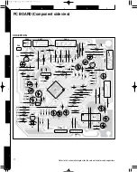
Страница 17: ... R45 R46 R15 R48 R43 R47 1 21 42 22 1 80 61 60 41 40 21 20 Q2 Q3 Q1 ZD1 CNP2 CNP5 CD SECTION CNP7 CNP8 CNP3 CNP4 CNP1 D1 D2 CN2 BI1 A C37 C6 C35 C5 C43 C45 R22 C23 C1 ZD2 C18 R7 R44 R9 C3 R10 R32 R38 R34 R36 R18 R29 R28 R33 R35 R31 R37 R2 R5 R1 R4 R6 R3 R19 C24 L1 J1 J2 J4 J5 R20 J16 J18 J19 J20 R21 J27 J31 J34 J35 J38 J39 J40 J41 J42 J43 J45 J46 J47 J48 C9 C10 C39 C40 C41 C11 R30 R49 J49 C14 C16 ...

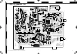
Страница 18: ... IN CNP301 WT902 C627 C628 C864 C863 C618 C617 C859 C123 C855 C124 C852 C856 C602 C606 C619 C629 C630 C621 C620 C622 C623 C625 C626 C624 C613 C614 R855 R856 R852 R853 J858 R866 R867 J604 C850 C860 J855 R382 R392 R391 C394 T303 C380 C391 C396 ZD351 C398 CF351 C352 C362 C321 X351 XT21 C364 CF352 T351 CF302 CF301 L352 L352 L354 L341 LT22 LT21 L342 FE301 C370 C393 X352 L351 C358 C357 C371 C372 C368 C3...

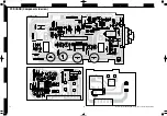
Страница 19: ... R810 R811 C804 J809 J808 J807 J806 C803 C817 C805 C820 1 8 1 O G I 5 C816 C815 1 8 J922 J931 J934 J933 J932 J920 LG901 J901 J912 J900 C921 C922 C915 R917 R918 C901 C902 R943 R941 R942 C946 C905 C956 C957 C919 C920 R954 R946 R948 R947 R945 R953 FH813 FH814 C819 C818 C916 C925 J918 J917 J924 J925 J915 J916 J909 J913 J914 RL801 J938 J923 J930 C958 J919 J941 J940 J939 C904 C903 T5A L 250V T5A L 250V ...

Страница 20: ...I905 SW718 FW701 A CNS701 CNS702 D711 Q700 Q703 Q709 Q713 LED700 LED709 C704 C700 C702 C701 C707 C563 C564 C570 C708 R563 R564 C717 XL700 VR701 J717 J718 J719 J723 J721 J728 R579 J701 J702 J703 J704 J705 J707 J708 J779 J780 R701 R703 R702 R709 R710 R711 R712 R713 R714 R715 R716 R708 J720 J722 J724 R720 R718 R719 J748 R726 R727 R728 R725 R781 R724 J749 J706 R729 R733 R734 R737 R738 R736 R775 R735 J...

Страница 21: ...1 0 022 T306 4 5 1 6 C335 560P 2 C323 0 022 6 1 C334 22P R323 68K R336 10K AM LOW CUT AM RF IN AM OSC IN AM OSC OUT FM AFC VSM 3 9K 0 022 21 22 23 24 19 20 C367 2 3 4 C330 15P T303 C331 0 047 C342 0 022 R365 10K C362 3 3u50 R350 2 2K R363 R364 2 2K 0 027 0 027 C369 27P C374 C373 L ch OUT R ch OUT MPX VCO FM AM OUT MPX IN MO ST 16 17 18 14 15 C372 X351 C368 1u50 1u50 C371 1u50 13 R361 3 3K R362 3 3...

Страница 22: ...N XIN XOUT XVDD RVDD RCHO RVSS LVSS LCHO LVDD FDO SPDO SLDO NC CONT4 CONT5 NC SBCK FG NC NC NC NC NC NC NC NC VSS VDD DOUT TEST SLC0 SLCIST EFMIN RF RFVDD RSVSS FIN1 A FIN2 B TIN1 E TIN2 F VREF REF1 NC TEC NC NC JITTC ADAVDD ADAVSS TDO 21 20 19 18 17 16 15 14 13 12 11 10 9 8 7 6 5 4 3 2 1 MUTE VREF STAND VCC SLDO SL SL GND GND GND GND GND GND TR TR FO FO NC FD TO 22 23 24 25 26 27 28 29 30 31 32 3...

Страница 23: ...18 0 1 3W C924 0 022 R920 1 5K R922 100 1 4W R911 100u100 C957 C920 100u100 3 9K R951 R952 3 9K 100 1 4W R912 C919 100u100 100u100 C956 47P C911 R909 0 22u50 C918 0 22u50 C917 220P C939 1K R905 1K R906 R910 220P C940 R944 33K 0 1u50 C905 390 R907 47u50 C915 47u50 C916 390 R908 R904 56K 1K R902 56K R903 C913 47P R901 1K 47P C914 C912 47P 10 1 2W R927 10 1 2W R925 0 29uH L901 0 29uH L902 R926 10 1 2...

Страница 24: ...M C567 56K R573 470K R575 0 022 180K 0 022 C571 R580 C569 15K R579 150K R577 270 1 4W R563 R564 270 1 4W 0 022 C573 680 RD09 820 RD10 RD11 1K 1 5K RD12 RD13 2 2K RD14 2 7K 3 9K RD15 5 6K RD16 680 RD04 820 RD05 RD06 1K RD07 1 5K 2 2K RD08 RD01 680 RD02 820 RD03 1K 28 29 30 36 39 36 39 32 33 31 3 1 2 3 1 2 RD17 10K RD18 18K R722 1K 1K R723 3 3u50 C707 15V 5V 12V 5V 5V 5V 5V B 12V 12V 5V 5V 5V 12V 5V...

Страница 25: ...2 63 60 47 56 62 41 38 844 6 5 5 5 1 2 FM DM SW4 AN AN AR AS AQx2 AQx2 803 804 858 859 AL AL SCREW AM ø3x8 AN ø2 6x6 AQ ø2x3 AR WASHER AS ø2x5 N09 5335 08 N09 5332 08 N32 2606 46 N30 2003 46 N19 1435 05 N86 2005 46 24 43 35 66 M3 SW1 SW2 SW3 54 32 57 53 39 39 39 39 39 PWB C PWB F PWB B 1 2 3 A B EXPLODED VIEW CD MECHANISM ...

Страница 26: ... K K K K K C B Bx2 B A A A A C Ex2 Ex2 Ex2 L B 674 753 717 656 635 630 734 786 654 752 628 655 649 649 649 629 791 705 747 681 624 643 643 620 639 640 748 706 704 785 751 629 787 630 624 615 780 614 616 627 675 676 782 610 611 609 608 612 613 642 641 660 607 BM BS1 BS2 601 603 602 643 643 PR1 RPEH PR2 PF A B C N09 5330 08 N09 5331 08 N09 5334 08 3x12 3x10 D E F N09 5335 08 N09 5338 08 N09 5343 08 ...

Страница 27: ...Korea M Other Areas indicates safety critical components Ref No Add ress New Parts Parts No Description Desti nation Re marks 601 1C A02 3014 08 CABINET TOP GCAB 1195AWSA 602 1C A02 3015 08 CABINET R GITAS0092AWSA 603 1C A02 3016 08 CABINET L GITAS0075AWSA 607 2C A21 3957 08 DRESS RING KNOB HDECQ0703AWSA 608 2C A21 3958 08 CASSETTE LID L GCOVA1365AWSA 609 2C A21 3959 08 CASSETTE LID R GCOVA1366AWS...

Страница 28: ...ndinavia K USA P Canada R Mexico C China I Malaysia Y PX Far East Hawaii T England E Europe G Germany V China Shanghai Y AAFES Europe X Australia Q Russia H Korea M Other Areas indicates safety critical components Ref No Add ress New Parts Parts No Description Desti nation Re marks 675 2C T90 0879 08 LOOP ANTENNA QANTL0008AWZZ 676 2C T90 0883 08 FM LEAD ANTENNA FANT1535A 681 2D W04 0019 08 MECHANI...

Страница 29: ... E Europe G Germany V China Shanghai Y AAFES Europe X Australia Q Russia H Korea M Other Areas indicates safety critical components Ref No Add ress New Parts Parts No Description Desti nation Re marks C366 CK73EB1H102K CHIP C 1000PF K C367 368 CE04KW1H010M ELECTRO 1 0UF 50WV C369 CC73ECH1H270J CHIP C 27PF J C370 372 CE04KW1H010M ELECTRO 1 0UF 50WV C373 374 CK45FB1H273K CERAMIC 0 027UF K C380 CE04K...

Страница 30: ...ysia Y PX Far East Hawaii T England E Europe G Germany V China Shanghai Y AAFES Europe X Australia Q Russia H Korea M Other Areas indicates safety critical components Ref No Add ress New Parts Parts No Description Desti nation Re marks CT1 2 CK45FB1C102K CERAMIC 1000PF K CT21 CE04KW1E470M ELECTRO 47UF 25WV ETE2 CT22 CK45FB1H223K CERAMIC 0 022UF K ETE2 CT23 CC45FSL1H220J CERAMIC 22PF J ETE2 CT24 CE...

Страница 31: ...urope X Australia Q Russia H Korea M Other Areas indicates safety critical components Ref No Add ress New Parts Parts No Description Desti nation Re marks MJ311 RK73EB2B000J CHIP R 0 J 1 8W ETE2 MJ314 RK73EB2B000J CHIP R 0 J 1 8W MXM3M5 MJ315 316 RK73EB2B000J CHIP R 0 J 1 8W ETE2 R11 RK73EB2B103J CHIP R 10K J 1 8W R12 RK73EB2B331J CHIP R 330 J 1 8W R13 17 RK73EB2B102J CHIP R 1 0K J 1 8W R23 RK73EB...

Страница 32: ...England E Europe G Germany V China Shanghai Y AAFES Europe X Australia Q Russia H Korea M Other Areas indicates safety critical components Ref No Add ress New Parts Parts No Description Desti nation Re marks R704 706 RK73EB2B102J CHIP R 1 0K J 1 8W R731 RK73EB2B103J CHIP R 10K J 1 8W R739 745 RK73EB2B102J CHIP R 1 0K J 1 8W R747 RK73EB2B101J CHIP R 100 J 1 8W R750 RK73EB2B225J CHIP R 2 2M J 1 8W R...

Страница 33: ...arts Parts No Description Desti nation Re marks IC860 KIA4558P ANALOGUE IC VHIKIA4558P 1 IC901 STK41203 IC VHISTK41203 1 67 IC901 STK4121J IC VHISTK4121J 1 12345 Q1 KTA1266GR TRANSISTOT VSKTA1266GR 1T Q2 KTC3203Y TRANSISTOR VSKTC3203Y 1T Q3 KRC102M TRANSISTOR VSKRC102M 1T Q103 106 2SC1845F TRANSISTOR VS2SC1845F 1T Q107 108 KTC3199GR TRANSISTOR VSKTC3199GR 1T Q109 KTA1266GR TRANSISTOT VSKTA1266GR 1...

Страница 34: ...er class 1 IEC Wow Flutter Less than unmeasurable limit General Power consumption 130 W Dimensions W 270 mm 10 5 8 H 330 mm 13 D 390 mm 15 3 8 Weight net 9 3kg 20 5lb SPECIFICATIONS 14 6 Dogenzaka 1 chome Shibuya ku Tokyo 150 8501 Japan KENWOOD SERVICE CORPORATION P O BOX 22745 2201 East Dominguez St Long Beach CA 90801 5745 U S A KENWOOD ELECTRONICS CANADA INC 6070 Kestrel Road Mississauga Ontari...

Отзывы: