Note that the current limiter may sometimes deviate
several digits from the specified current limit value. If the
current limiter is used within the smaller range of error,
connect each output pin to the ground level and place
the s y s t e m in the overload s t a t u s , and then use this
products after setting a desired current limiter value.
If rather a large-capacitance load is connected to this
product, it will take some seconds until the stable vol-
tage level is reached. Keep it in mind.
T h e positive, negative pins and the C O M pin of this
product have a capacitor of 1 0 0 micro farad. This product
has an internal circuit for the discharge. This internal cir-
cuit becomes active w h e n the output mode is set to O F F .
T h i s means that the diodes in serial w i t h a load are re-
quired to prevent the discharge if the products is used
a s a battery charger or a memory backup battery.
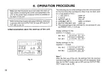
6-3 Tracking Power Supply Procedure
1) S e t the L E D s a s s h o w n is Figure 9.
(Be sure that the O U T P U T L E D © is not lit.)
Figure 9 indicates the c a s e w h e r e positive voltage level is
used.
2) Turn the Rotary Encoder to set an arbitrary positive voltage
value.
3) Press the A K E Y © and make sure that the«A L E D lights up.
4) Turn the Rotary Encoder to set an arbitrary positive current
value.
5) If the - 1 8 V K E Y is pressed, the display of each of the volt-
meter and the ammeter allows the user to confirm that the
negative value is the s a m e a s the positive.
6) Press the O U T P U T K E Y © to obtain the output value en-
tered from the positive ( + ), or negative { - ) , output terminal.
7) If the Rotary Encoder is turned in the state of 6) above, the
negative values change. Press the + 1 8 V K E Y to make sure
that the positive v a l u e s are changing alike.
2 1
Fig. 9


