


PW-A
31
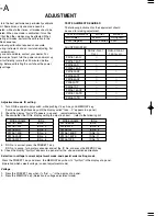
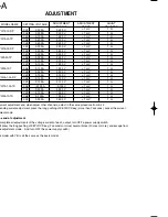
ADJUSTMENT
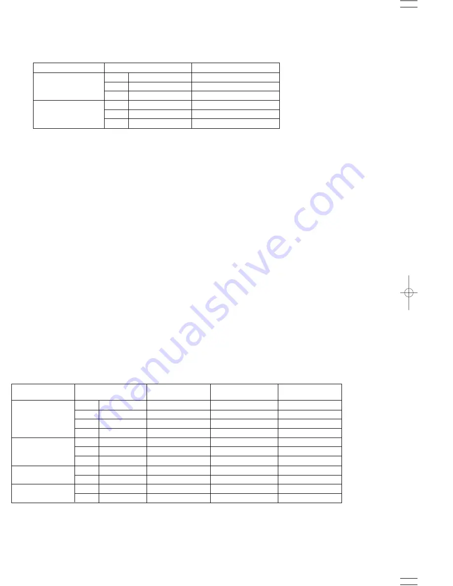
MODEL NAME
SETTING VOLTAGE
ADJUSTMENT RANGE
CH1
1.800 V
CH2
-1.800 V
PW18-1.3ATS
CH3
0.600 V
CH1
2.600 V
CH2
-2.600 V
PW26-1ATS
CH3
0.600 V
After voltage adjustment end, when adjust other channels, adjust in the same procedure from 5-3-2.
When ending voltage adjustment, press the long pushing of KEYLOCK key (more than 2 seconds) Cancel the
voltage adjustment mode.
3-1. Current
3-2. Current adjustment channel setup
3-4. Current rating 100% adjustment
3-3. Connection of constant apparatus
1. Press the PRESET 2 key when it's "Ajst ---" in the display of a panel. (Even if press the LED of PRESET 2
key, it is not turned on)
2. Press the MEMORY key (Selection in current adjustment mode)
1. Press the A key.
2. Turn a rotary encoder and set the adjusting channel.
3. Press the MEMORY key.
4. Select the OUTPUT SELECT of the channel to adjust.
1. Connect the output CH to adjust PWA and COM terminal to shunt register.
2. Connect the sensing terminal of shunt register to DMM.
1. Set up a current display in DIGIT key and a rotary encoder. (refer to the following list)
2. Turn on MAIN OUTPUT.
3. Adjust in DIGIT key and a rotary encoder so that it becomes within the limits of the following list of the value of
DMM.
4. Press the MEMORY key.
MODEL NAME
SETTING VOLTAGE
ADJUSTMENT
VOLTAGE
ADJUSTMENT
RANGE
SHUNT
REGISTER
CH1
1.800 A
1.800 V
1
Ω
1
Ω
1
Ω
1
Ω
1
Ω
1
Ω
CH2
-1.800 A
-1.800 V
CH3
2.000 A
2.000 V
PW18-1.8AQ
CH4
1.000 A
1.000 V
CH1
1.300 A
1.300 V
CH2
-1.300 A
-1.300 V
PW18-1.3AT
CH3
5.000 A
0.500 V
±
0.1 mV
±
0.1 mV
±
0.1 mV
100 m
Ω
100 m
Ω
100 m
Ω
CH1
3.000 A
0.300 V
PW18-3AD
CH2
-3.000 A
-0.300 V
CH1
1.500 A
1.500 V
1
Ω
1
Ω
PW36-1.5AD
CH2
-1.500 A
-1.500 V
±
1 mV
±
1 mV
±
1 mV
±
1 mV
±
1 mV
±
1 mV
±
1 mV
±
1 mV
±
1 mV
±
1 mV
±
1 mV
±
1 mV
±
1 mV
±
1 mV
Содержание PW-A series
Страница 57: ...A C E G I B D F H J SCHEMATIC DIAGRAM PW A ...
Страница 58: ...SCHEMATIC DIAGRAM L N P R T M O Q S PW A ...
Страница 59: ...SCHEMATIC DIAGRAM U W Y AA AC V X Z AB AD PW A ...
Страница 60: ...AF AH AJ AL AN AG AI AK AM SCHEMATIC DIAGRAM PW A ...
Страница 61: ...AO AQ AS AU AW AP AR AT AV AX SCHEMATIC DIAGRAM PW A ...
Страница 62: ...PW A Y39 4160 00 AY BA BC AZ BB ...
Страница 63: ...BE BG BI BK BM BF BH BJ BL SCHEMATIC DIAGRAM PW A ...
Страница 64: ...BN BP BR BT BV BO BQ BS BU BW SCHEMATIC DIAGRAM PW A ...
Страница 72: ...PW A A product of KENWOOD TMI CORPORATION 1 16 2 HAKUSAN MIDORI KU YOKOHAMA CITY 226 8525 JAPAN ...


