


PW-A
28
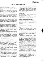
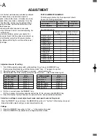
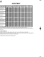
ADJUSTMENT
To ob tain the best performance, periodically calibrate
the unit. Sometimes, only one mode need be
calibrated, while at other times, all modes shou ld be
calibrated. When one mode is calibrated, it must be
noted that the other modes may be affected. When
calibrating all modes, perform the calibration in the
specified sequence.
The following calib ration required an accurate
measuring instrument and an insulated adjusting flat
blade screwdriver.
If they are not available, contact your dealer. For
optimum adjust ment, turn the power on and warm up
the unit sufficiently (more than 30 minutes) before
starting. Before calibrating the unit check the power
supply voltage.
TEST EQUIPMENT REQUIRED
The following instrument or their equivalent should
be used for making adjustment.
TEST EQUIPMENT
MODEL
MAKER
Multi-meter
34401A
HP(Agilent)
Shunt Register
RUG-Z series
PCN
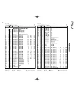
SHUNT REGISTER
RUG-Z-1R-0.1
1[
Ω
]
[ m
Ω
]
RUG-Z-100-0.1
100
PW18-1.8AQ
PW18-1.3AT
PW18-3AD
PW36-1.5AD
PW18-3ADP
PW18-2ATP
PW16-5ADP
PW8-3ATP
PW26-1AT
PW36-1.5ADP
PW18-1.3ATS
PW26-1ATS
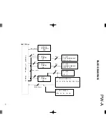
1-1.
Adjustment mode ID setting
1. Turn ON the power supply switch, while pushing V key, A key and MEMORY key.
(Continue pushing Above key until the display called "Idno -- X" appears in a panel)
2. Check the display "Ajst Id X" appears in a panel.
(adjustment mode)
3. Check whether the ID No. display setting to adjust is correct.
(refer to the following list)
MODEL NAME
ID No.
MODEL NAME
ID No.
PW18-1.8AQ
ID No. 1
PW16-5ADP
ID No. 7
PW18-1.3AT
ID No. 2
PW8-3ATP
ID No. 8
PW18-3AD
ID No. 3
PW26-1AT
ID No. 9
PW36-1.5AD
ID No. 4
PW36-1.5ADP
ID No. 10
PW18-3ADP
ID No. 5
PW18-1.3ATS
ID No. 11
PW18-2ATP
ID No. 6
PW26-1ATS
ID No. 12
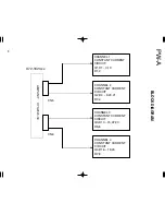
4. If ID No. is correct, press the PRESET 1 key.
If ID No. is wrong, turn a rotary encoder and set the ID No. and press the MEMORY key.
5. Check the display "Ajst Ajst" appears in a panel after the above-mentioned directions
1-2.
Selection in voltage / current adjustment mode, and special order setting mode
Press the PRESET 1 key and press the MEMORY key when it’s "Ajst Ajst" in the display of a panel.
(Operation which selects voltage / current adjustment mode)
2-1.
Voltage
1. Press the PRESET 1 key when it’s "Ajst ----" in the display of a panel.
2. Press the MEMORY key. (Selection in voltage adjustment mode)
‡
‡
‡
‡
‡
‡
‡
‡
‡
‡
‡
‡
‡
‡
‡
‡
‡
‡
‡
‡
Содержание PW-A series
Страница 57: ...A C E G I B D F H J SCHEMATIC DIAGRAM PW A ...
Страница 58: ...SCHEMATIC DIAGRAM L N P R T M O Q S PW A ...
Страница 59: ...SCHEMATIC DIAGRAM U W Y AA AC V X Z AB AD PW A ...
Страница 60: ...AF AH AJ AL AN AG AI AK AM SCHEMATIC DIAGRAM PW A ...
Страница 61: ...AO AQ AS AU AW AP AR AT AV AX SCHEMATIC DIAGRAM PW A ...
Страница 62: ...PW A Y39 4160 00 AY BA BC AZ BB ...
Страница 63: ...BE BG BI BK BM BF BH BJ BL SCHEMATIC DIAGRAM PW A ...
Страница 64: ...BN BP BR BT BV BO BQ BS BU BW SCHEMATIC DIAGRAM PW A ...
Страница 72: ...PW A A product of KENWOOD TMI CORPORATION 1 16 2 HAKUSAN MIDORI KU YOKOHAMA CITY 226 8525 JAPAN ...


