


REGULA
TED
DC
POWER
SUPPLIES
AC Power ON/OFF Control
The power protection device (AC power relay) can be controlled on
/off from an external signal (provided that the power switch is on).
CV/CC Monitoring
●
A monitoring output from about 0 V to 1/10 the rated voltage
can be output with respect to the output voltage from 0 V to the
rated voltage.
●
A monitoring output from about 0 V to 10 V can be output with
respect to the output current from 0 A to the rated current.
Control by an External resistance of Output Voltage and Current
61
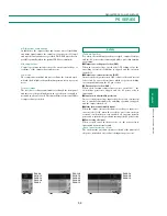
Remote Sensing
This function prevents the voltage
drop which is caused by the load
connection resistance and the
stability degradation caused by the
contact resistance, and compensates
for the voltage drop of up to 1 V
per path provided that the output
terminal voltage is within the rated
voltage.
Output ON/OFF Control
The output can be turned on/off with
an external signal. The output can also
be fixed to on while power is on.
Control by an External Voltage of Output Voltage and Current
Functions for system power supply
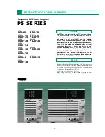
PS SERIES
REGULATED DC POWER SUPPLIES
PS
SERIES
I
O
E
O
J
1
+
−
I
O
External resistance
(0 to10k )
E
O
R
1
/R
2
R
1
R
2
External resistance
(0 to10k )
Output
current
Output
voltage
I
O
E
O
Output
current
Output
voltage
I
O
r
E
L
+
S
−
S
r
E
O
J
2
+
−
Load
I
O
E
O
J
1
Vcc
Cont. item
Control Resistance
Current flowing
Input Common
Normal
Fail safe
a resistance
Output voltage 0 to approx.10k
Ω
∞
to 0
Ω
Approx. 1mA or less
+
S terminal
Output current 0 to approx.10k
Ω
【∞
to 0
Ω】
Approx. 1mA or less
+
S terminal
I
O
E
O
J
2
CV. Monitor
CC. Monitor
Items
Control contents
Input control signal
In/Out Common
Connector
Output voltage
Output voltage
0 to 10V/0 to10k
Ω
,
∞
to 0
Ω
+
S terminal
J
1
Output current
Output current
0 to 10V/0 to10k
Ω
,
∞
to 0
Ω
+
S terminal
J
1
Output ON/OFF
Output ON
Photo diode ON
Floating(Community common)
J
1
Power ON/OFF
AC power relay ON
Photo diode ON
Floating(Community common)
J
1
CV. mode signal
At CV operation
Photo transistor ON
Floating(Community common)
J
1
CC.mode signal
At CC operation
Photo transistor ON
Floating(Community common)
J
1
Power on signal
At power on
Photo transistor ON
Floating(Community common)
J
1
OVP signal
At OVP operation
Photo transistor ON
Floating(Community common)
J
1
Alarm signal
At OCP, OHP operation, power off
Photo transistor ON
Floating(Community common)
J
1
/J
2
Output voltage monitor
For output 0V to rated voltage
0V to
1
/
10
×
rated voltage
+
S terminal
J
2
Output current monitor
For output 0A to rated current
0V to 10V
+
S terminal
J
2
Input
signal
O
utput
signal
*
Each of the Floating (Common) input/output signals passes through a photo coupler and uses a diode input and open collector output. Their common
terminal is common.
* The alarm signal is also output during the operation of the input current protection circuit or input over-voltage protection circuit.
Applications - Remote Control Operations
Control item
Control signal
Input Common
Output
ON
Photo diode ON
Floating
OFF
Photo diode OFF
(Community common)
Control item
Control Voltage Input impedance
Input Common
Output voltage 0 to Approx. 10V Approx. 10k
Ω
+
S terminal
Output current 0 to Approx. 10V Approx. 10k
Ω
+
S terminal
I
O
E
O
J
1
+
−
I
O
E
2
E
O
E
1
/E
2
E
1
External voltage
(0 to10V)
Output
current
Output
voltage
External voltage
(0 to10V)
I
O
E
O
J
1
Vcc
Without sensing
E
L
E
O
I
O
E
L
E
O
I
O
2r
×
I
O
2r
×
I
O
With sensing
Control item
Control signal
Input Common
AC power
ON
Photo diode ON
Floating
relay
OFF
Photo diode OFF
(Community common)


