3
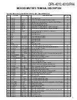
System Microcomputer MS101C15FCJ (IC1: Main PWB Unit)
Pin No.
Pin Name
Signal Name
I/O
Purpose/Description
Normal Operation
Level
1
VREF (–)
Connected to GND
2
PA0/AN0
CD_EJ
I
CD/EJ_SW detection terminal [H: Normal. L: Eject]
L (a)
3
PA1/AN1
TYPE
I
Destination type selection input [H: J Type. M: K Type. L: M Type]
–
4
PA2/AN2
REEL_S
I
REV reel pulse detection terminal
H/L
5
PA3/AN3
REEL_T
I
FWD reel pulse detection terminal
H/L
6
PA4/AN4
AM_SD
I
AM SD input [H: Station detected. L: Station not detected]
H (a)
7
PA5/AN5
FM_SA
I
FM SD input [H: Station detected. L: Station not detected]
H (a)
8
PA6/AN6/
NC
I
–
9
PA7/AN7
SMALL
I
SMALL detection input [H: SMALL off. L: SMALL on]
L (a)
10
VREF (+)
Connected to BU 5 V
11
Vdd
Connected to Vdd
12
OSC2
X’Tal (8. 38)
X’tal (connected to 8.38 MHz)
13
OSC1
X’Tal (8. 38)
X’tal (connected to 8.38 MHz)
14
Vss
Connected to GND
15
Xl
Connected to GND
16
XO
Open
17
MMOD
Connected to GND
18
P00/SBO0/TXD
C_MAIN_M
O
C-mechanism motor control [H: ON. L: OFF]
H (a)
19
P01/SBI0/RXD
INPUT_SEL1
O
E_VOL input switching control (in combination with pin 20)
H/L
20
P02/SBT0
INPUT_SEL2
O
[HL: CD. LH: Tape. LL: Tuner]
H/L
21
P03/SBO1
CH_DATAH
O
Data output to CD-CH
H/L
22
P04/SBI1
CH_DATAC
I
Data input from CD-CH
H/L
23
P05/SBT1
CH_CHCLK
I/O
Previous bus: Data input from CD-CH. New bus: Data output to CD-CH.
H/L
24
P06/BUZZER/DK
BEEP
O
Beep output [Permanently L]
L
25
P27/RESET
RESET
I
System reset [H: Operation. L: Reset]
L (a)
26
P10/TM010/RMOUT
CH_REQH
O
Send request output to CD-CH
L (a)
27
P11/TM1IO
CH_CHCON
O
CD-CH operation control
H (a)
28
P12/TM2IO
CH_CH1/2
O
CD-CH 1/2 switching output
29
P13/TM3IO
PNL_OPEN
I
Panel open detection [H: Closed. L: Open]
L (a)
O
Test point (Valid only in test mode). [Permanently L]
L
I
Back_Up detection input [H: Power down. L: Normal]
H (a)
I
Send request input from CD-CH
L (a)
I
Send request input from PNL_
µ
COM
H (a)
I
Destination type selection input (for genuine model)
–
I
Acc detection input [H: Acc OFF. L: Acc ON]
H (a)
CD_DATA
I/O
Data input/output from/to CD mechanism
H/L
I
Not used (Open)
–
O
CLK output to CD mechanism
H/L
O
C-mechanism loading motor control
H (a)
40
P34/BT
C_SUB_M–
O
C-mechanism loading motor control
H (a)
41
P35/LDDMA
C_MSC
O
Blank detection mode control [H: G2 (in play mode). L: G1 (in FF mode)]
H/L
42
P36/STDMA
C_NR
O
Dolby ON/OFF control
H (a)
43
P37/DKDMA
C_MS_IN
I
Blank pulse detection input
H/L
44
P40/KEY0
C_MTL
O
Metal ON/OFF control.
H (a)
45
P41/KEY1
C_MODE2
I
Sub-motor control terminal 2
H/L
46
P42/KEY2
C_MODE3
I
Sub-motor control terminal 3 (cassette pack IN detection terminal)
H/L
47
P43/KEY3
C_MODE1
I
Sub-motor control terminal 1
H/L
48
P44/KEY4
DSP_DATA
O
DATA output to DSP
H/L
49
P45/KEY5
DSP_CLK
O
CLK output to DSP
H/L
50
P46/KEY6
DSP_STB
O
LATCH output to DSP
H/L
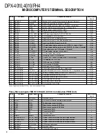
MICROCOMPUTER’S TERMINAL DESCRIPTION
DPX-4010,4010/PH4
www. xiaoyu163. com
QQ 376315150
9
9
2
8
9
4
2
9
8
TEL 13942296513
9
9
2
8
9
4
2
9
8
0
5
1
5
1
3
6
7
3
Q
Q
TEL 13942296513 QQ 376315150 892498299
TEL 13942296513 QQ 376315150 892498299


