7
ADJUSTMENT
DPX-3030/MP4030
TU
101
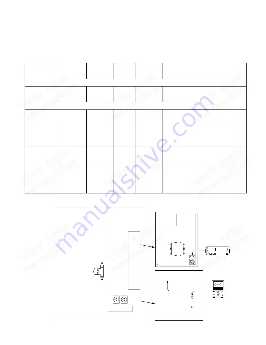
VR201B
Rch
VR201A
Lch
MAIN PWB UNIT
DC voltmeter
(a) 0V
T
TP
TU101
FWD
REV
(b)
TUNER UNIT
TUNER UNIT
Dolby Level
MAIN PWB UNIT (foil side)
(c) 388mV
AC voltmeter
TO GND
DOLBY Lch
DOLBY Rch
• Setting for the unit condition as follows.
BALANCE/BASS/TREBLE/FADER : Center Position, DOLBY/LOUD/DSP : OFF
TUNER BAND : FM
No.
ITEM
INPUT
OUTPUT
TUNER
ALIGNMENT
ALIGN FOR
FIG
SETTINGS
SETTINGS
(RECEIVER)
POINT
SETTINGS
FM TUNER SECTION
1
DISCRIMINATOR
98.1MHz 0dbv,
Connect a DC
FM 98.1MHz
T F/E (TU101)
0V
(a)
60db
µ
, (ANT
Voltmeter to TP
input)
F/E (TU101)
TAPE DECK SECTION
1
CLEANING
-
-
-
PB Head, capstan,
Clean the PB Haed,capstan and pinch roller using a
-
pinch roller
cotton swab slightly damped with alcohol
2
AZIMUTH (Tape
MTT-902 Mirror
-
PLAY
Azimuth
Playing the mirror tape in FWD mode, adjust the
(b)
running condition)
Tape
adjustment screw
azimuth adjustment screw (A) and (B) so as to e
FWD (A), REV (B)
liminate a curl at the guides on both ends of head
while looking in to the mirror tape. After that you can
adjust same manner for the REV side.
3
AZIMUTH
TCC-153 10KHz,
Connect the AC
PLAY
Azimuth
Adjust the output to maximum and adjust the azimuth
(b)
-10db
Voltmeter and
adjustment screw
adjustment screw for the Lissajours waveform pattern
Oscilloscope to pri
FWD (A), REV (B)
of the oscilloscope to become close to a 45
°
straight
output terminal
line.
4
PLAY BACK LEVEL
TCC-130 400Hz,
Connect the AC
PLAY
VR201A (L),
388mV (-6dbs)
(c)
(Dolby Level)
Dolby
Voltmeter to
VR201B (R)
Adjust the L/R channel for FWD side.
between Dolby
After adjusting the FWD side, check the playback
level output and
level for the REW side so that the playback lever are
GND.
between 330mV to 480mV.
www. xiaoyu163. com
QQ 376315150
9
9
2
8
9
4
2
9
8
TEL 13942296513
9
9
2
8
9
4
2
9
8
0
5
1
5
1
3
6
7
3
Q
Q
TEL 13942296513 QQ 376315150 892498299
TEL 13942296513 QQ 376315150 892498299


