10
Kentech Instruments Ltd., Unit 9, Hall Farm Workshops, South Moreton, Didcot, Oxon, OX11 9AG, U.K.
10th. July 1999
1
11
12
13
14
15
16
17
18
19
2
3
4
5
6
7
8
9
10
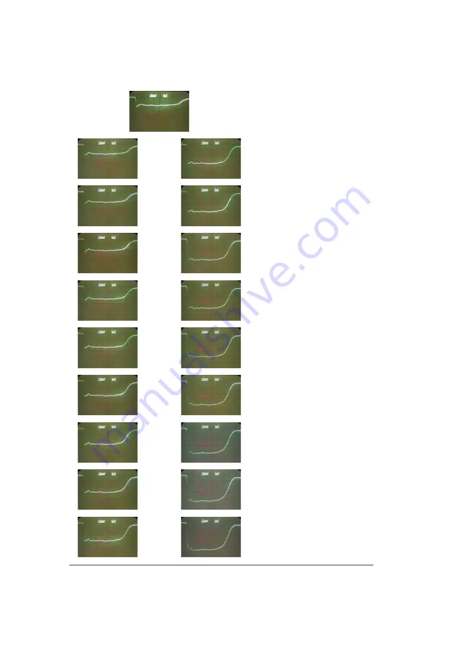
Figure 5
Output pulse shape one of four channels
100 volts per division and 5ns per division


