


FOR SERVICE TECHNICIAN’S USE ONLY
PART NO. W10035270
TECH SHEET - DO NOT DISCARD
PAGE 10
TEST #5
Moisture Sensor
NOTE:
This test is started with the machine
completely assembled.
This test is performed when an automatic
cycle stops too soon, or runs much longer
than expected.
NOTE:
Dryer will shut down automatically
after 2½ hours.
The following items are part of this system:
–
Harness/connection
–
Metal sensor strips
–
Machine control electronics
1.
Activate the diagnostic test mode and
advance past saved fault codes. See
procedure on page 1.
2.
Open the dryer door. If a continuous
beep tone is heard and an alphanumeric
number is displayed on the console as
soon as the door is opened, a short
circuit exists in the moisture sensor
system.
➔
If this doesn’t happen, go to step 3.
➔
Otherwise, go to step 4.
NOTE:
Over drying may be caused by a
short circuit in the sensor system.
3.
Locate the two metal sensor strips on the
face of the lint screen housing. Bridge
these strips with a wet cloth or finger.
➔
If a continuous beep tone is heard and
a software revision number is
displayed on the console, the sensor
passes the test. Go to step 8.
➔
If not, continue with step 4.
4.
Access the moisture sensor wires by
removing the front panel. See Removing
the Front Panel/Drum Assembly, page 11.
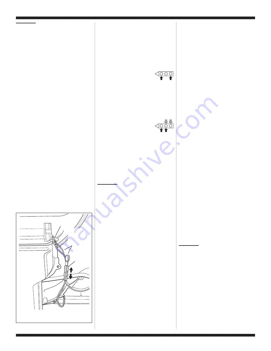
Disconnect the sensor connector. See
figure 11.
5.
Access the machine control electronics.
See Accessing & Removing the
Electronic Assemblies, page 11. Remove
the connector P13 from the circuit board.
Check the main harness connections
between the sensor connector and
machine control for a short or open
circuit.
➔
Replace the main harness if necessary.
➔
If harness is OK, continue with step 6.
6.
Measure the resistance
across the outermost
contacts of the sensor
connector that includes the two MOVs.
➔
If a small resistance is measured,
check for debris across moisture strips
inside of the drum; clean if debris is
present. If debris is not present,
replace sensor harness with MOVs.
➔
Otherwise go to step 7.
7.
Measure the resistance across
each of the outermost
contacts and the center
terminal (ground connection).
➔
If a resistance less than infinity is
measured, replace the sensor harness
with MOVs.
8.
If moisture sensor diagnostic test passes,
check the thermistor: Perform TEST #4a,
page 9.
➔
If the problem persists after replacing
the moisture sensor, harness with
MOVs and thermistor, replace the
machine control electronics.
TEST #6
Buttons and
Indicators
This test is performed when any of the
following situations occurs during the
Console Buttons and Indicators Diagnostic
Test, page 1:
✔
None of the indicators light up
✔
No beep sound is heard
✔
Some buttons do not light indicators
None of the indicators light up:
1.
See Diagnostic Guide/Before Servicing...
on page 1.
2.
Perform TEST #1, page 6 to verify supply
connections.
3.
Perform TEST #2, page 7.
4.
Perform steps in Accessing & Removing
the Electronic Assemblies, page 11 and
visually check that the P5 connector is
inserted all the way into the machine
control electronics.
5.
Visually check the user interface
assembly connections.
6.
If both visual checks pass, replace the
user interface assembly.
7.
Plug in dryer or reconnect power.
8.
Perform the Console Buttons and
Indicators Diagnostic test, page 1 to
verify repair.
9.
If indicators still do not light, the machine
control electronics has failed:
➔
Unplug dryer or disconnect power.
➔
Replace the machine control
electronics.
➔
Plug in dryer or reconnect power.
➔
Perform the Console Buttons and
Indicators Diagnostic test, page 1 to
verify repair.
No beep sound is heard:
1.
Perform steps in Accessing & Removing
the Electronic Assemblies, page 11 and
visually check that the P5 connector is
inserted all the way into the machine
control electronics.
➔
If visual check passes, replace the user
interface assembly.
2.
Plug in dryer or reconnect power.
3.
Perform the Console Buttons and
Indicators Diagnostic test, page 1 to
verify repair.
4.
If replacing the user interface assembly
failed:
➔
Unplug dryer or disconnect power.
➔
Replace the machine control
electronics.
➔
Plug in dryer or reconnect power.
➔
Perform the Console Buttons and
Indicators Diagnostic test, page 1
to verify repair.
Some buttons do not light indicators:
1.
Perform steps in Accessing & Removing
the Electronic Assemblies, page 11 and
visually check the user interface
assembly connections.
➔
If visual check passes, replace the user
interface assembly.
2.
Plug in dryer or reconnect power.
3.
Perform the Console Buttons and
Indicators Diagnostics test, page 1 to
verify repair.
TEST #7
Door Switch
Activate the diagnostic test mode as shown
on page 1, and perform the Door Switch
Diagnostic test, page 1. Functionality is
verified with a beep each time the door is
closed and opened, and a number and letter
appears in the display (i.e.,
0E
,
09
).
If any of these conditions are not met:
➔
Unplug dryer or disconnect power.
➔
Check that the wires between the door
switch and machine control electronics
are connected. See figure 12, page 11 for
switch location and see Removing the
Front Panel/Drum Assembly, page 11.
Lint Screen
Housing
Sensor
Connector
Sensor
Sensor Harness
with MOVs
(Metal Oxide
Varistors)
Figure 11.
Disconnect sensor
connector.


