Operational Check
Before installing the switch a simple operational check should be performed, as follows:
1. Fill a container with water
2. Open the electronics housing cover and connect power (see section on “
Wiring
”).
3. Set the Fail Safe jumper to the LLFS position (lower two pins).
4. Apply power
5. Place the sensor gap into the water.
a. Relay Version -- The relay will energize (the contacts between (NC) and (C) should open).
b. 2-wire Version -- The current in the Positive lead will be 20.0mA.
6. Remove the sensor from the liquid.
a. Relay Version – The relay will de-energize (the contacts between (NC) and (C) should close).
b. 2-wire Version – The current in the Positive lead will be 4.0mA.
7. Disconnect the wiring.
Mounting
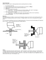
For threaded process connections, screw sensor into the opening using a wrench on the sensor mounting nut flats. Use
thread tape or suitable pipe compound on the threads. If flanged, bolt the sensor to the mating flange with the proper
gasket.
The sensor gap must protrude into the vessel / pipe being measured. The sensor will not function properly if the detection
tip is in a nozzle. See the following drawings for mounting guidelines:
Wiring
It is recommended that conduit be installed onto the ¾” NPT connection on the electronics housing. A seal drain fitting
should be used to prevent moisture from entering the switch. All wiring, conduit, and electrical fittings must conform to
local electrical codes for the location selected. If the switch is to be used in a Hazardous Area, the applicable codes of the
National Electrical Code must be followed as well.
DO NOT
use
housing to
tighten sensor
Use wrench here
¾” NPT
Turn slot
vertical allowing
media to fall
through
Vessel Wall
Slot must
extend at least
1” (25mm)
beyond end of
nozzle


