8
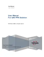
To mount the camera
1. Attach a string or plumb bob to the
ceiling tile with a thumb tack.
2. Position the string directly over
ample table space or work surface
to allow easy document and object
position.
See Figure 6
3. Using a sharp utility knife, score a
3 1/2” diameter hole into the front
of the tile centered on the string.
4. Cut out the 3 1/2” hole.
5. Place the tile support rail on the
back side of the tile and center over
the hole.
6. Rotate the camera enclosure
module so that the positioning
indicator is oriented toward the
monitor or display device. This
position is standard document
camera orientation.
See Figure 7
Note:
If the positioning indicator
is not oriented toward the
monitor or display device, your
image will not be oriented
properly
7. Fit the tile ring through the hole in
the tile, sandwiching the tile support
between the camera enclosure and
the tile. The camera tile ring will fit
into the 3 1/2” opening from the rear
of the tile.
See Figure 8
8. Position the tile above the ceiling.
9. Attach the white trim ring to the
camera enclosure from the front of
the tile and tighten gently. This will
pull the trim ring, camera module
and tile support rail together and
firmly hold the camera in position
against the ceiling tile.
Installation
Ceiling Tile
Trim Ring
Enclosure
Figure 6. Positioning the camera
Figure 7. Support braces on 2'x2' ceiling tile
Figure 8. Enclosure and trim ring side view
5
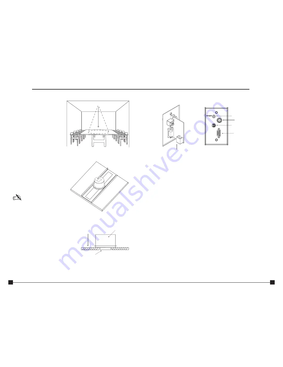
Front and back wall plate connections
A. RJ-45 Connector.
The RJ-45 jack connects to the RJ-45 connector on the camera
enclosure using a Cat. 5 cable
B. 15 VDC.
The 15 VDC power supply jack.
C. Composite.
This output jack allows the Ceiling DocCam™ II to be connected to video
display devices that require a composite signal such as codecs, TV monitors, VCRs
and LCD and DLP projectors.
D. S-Video.
This output jack allows the Ceiling DocCam II to be connected to video
display devices that require an S-video signal such as video conferencing systems,
video capture cards, TVs and video to USB adapters. If your video display device
has both S-Video and composite, use S-video for the highest quality image.
Both the S-Video and composite outputs are always live making it possible to connect
the camera to two separate display devices at the same time.
E. RS-232.
This output allows you to connect the camera to control systems such as
Crestron or AMX.
A
C
D
E
B
15 VDC
Composite
Video
S-Video
RS-232
Figure 3. Front and back wall plate
Introduction