14
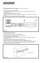
C-2 Attaching the Fan to the Wall
(only for units with 2,2 kW fans)
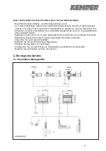
• Drill the four holes required for installation.
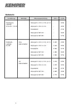
The dimensions for the mounting holes can be found in the diagram illustration 2 and the
measurements table.
• Attach the fan with suitable dowels and screws.
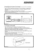
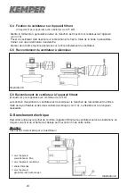
• Connect the adapter and the silencer to the discharge side of the fan as shown in the above
diagram.
• Hook the free end of the silencer onto the bracket supplied.
C-3 Mounting the Filter Unit
• Open the service door and remove the filter elements.
• Attach the brackets for mounting the unit to the rear of the unit.
• Drill the four holes required for installation.
The dimensions for the mounting holes can be found in the diagram illustration 2 and the
measurements table.
• Mount the unit on the wall using suitalbe dowels and screws.
• Attach the control box to the wall below the filter unit at a heigt of about 1.5 m.
• Install the extractor arm(s) or crane(s) as shown in the corresponding Operating Instructions.
• Replace the filters in the unit. Make sure in this context that the arrow on the front of the
collector cell points upwards (air flow direction).
Illustration 3
Illustration 4
Back of unit
Содержание 150 0002
Страница 2: ......
Страница 50: ...48 I 2 Filtergerät Filter Unit 3 phase current Unité de filtration 3 Ph Drehstrom courant triphasé ...
Страница 51: ...49 I 3 Control Box Control Box Boîtier de commande 3 Ph Drehstrom 3 phase current courant triphasé ...
Страница 53: ...51 I 5 Filterüberwachung Filter Monitor Contrôle de saturation ...
Страница 54: ......
Страница 55: ......
Страница 56: ......


