


KCO-NO2 User’s Manual
90-0201-01
Kele • 3300 Brother Blvd. • Memphis, TN 38133
Page: 7
WWW.KELE.COM
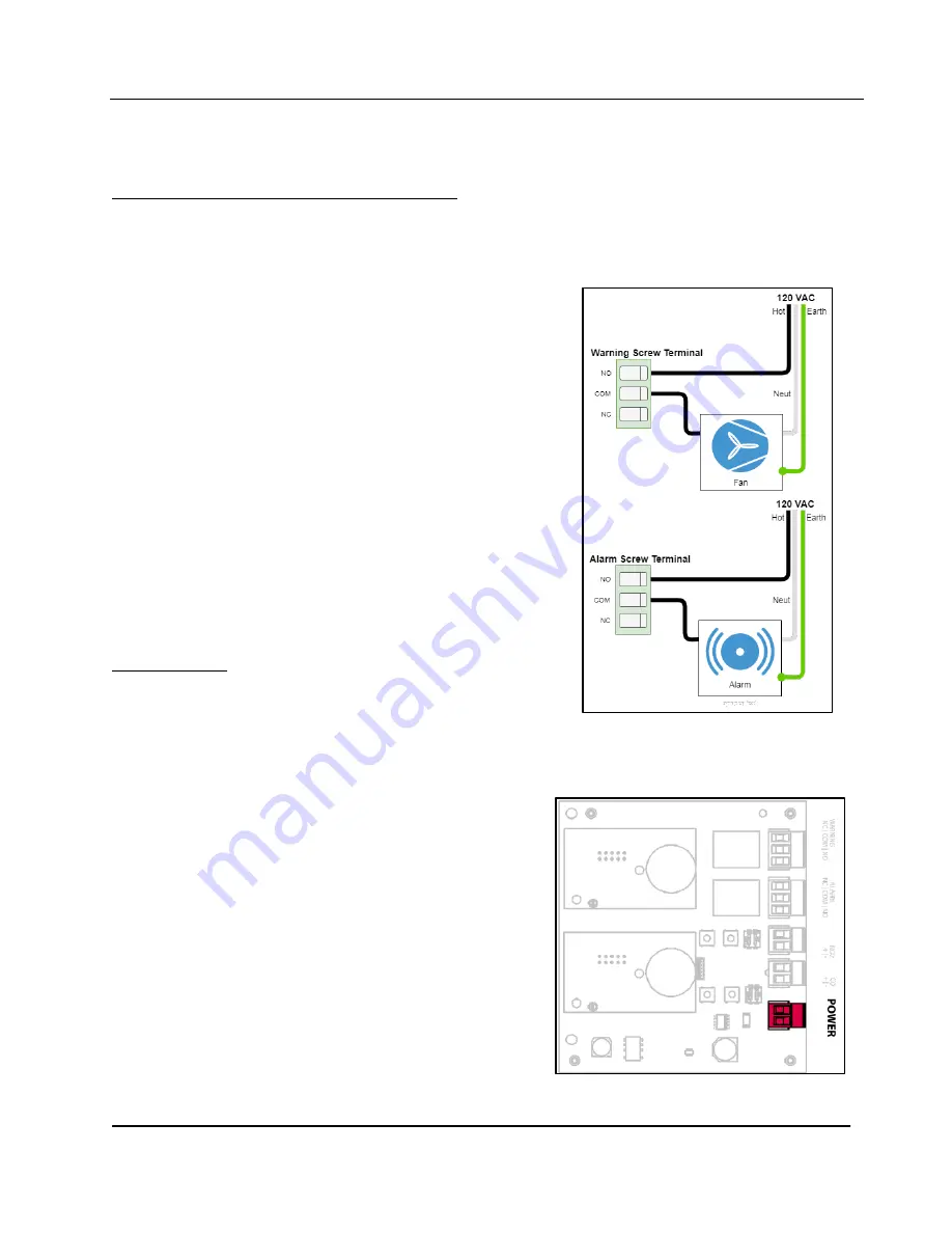
FIGURE 5:
Example wiring Diagram for
Normally Open Operation.
FIGURE 6
: Location of Power Connector
An example wiring diagram for relay connections is provided in Figure 5. When wired as shown,
the fan will be energized in both warning and alarm conditions and the alarm will be energized only
in the alarm condition.
To wire the
Warning
and
Alarm
relay outputs:
1.
Determine if the device being attached to the relay output should be wired in NO or NC
configuration.
2.
Unplug the relay output screw terminal.
3.
Connect the power source voltage for the device
being attached to the controller’s relay output to
either the
NO
or
NC
location of the screw terminal
4.
Wire the power input of the device being attached
to the controller’s relay output to the
COM
location
of screw terminal.
5.
Plug the relay output screw terminal back into the
correct location on controller board.
3.3 Power Connection
Power connection to the controller is made at the two-
terminal screw connector located at the bottom-right side
of the board (highlighted in Figure 6). Power to the
controller can be either AC or DC voltage; DC voltage can
be connected in either polarity.
The input power is electrically isolated from the analog
outputs.
To wire power:
1.
Open the controller’s enclosure and unplug the
screw terminal labeled
POWER
on the controller
board.
2.
Attach power wires to the screw terminal ensuring
the connection is snug.
3.
Plug the screw terminal back into the
POWER
receptacle on the controller board: this will
cause the controller to power up and begin
operation.
It is recommended that all wired connections are
connected prior to providing power to the controller:
see the following sections for details on making these
connections.


