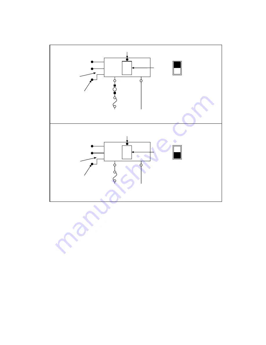
manualshive.com logo in svg
background image


5


Figure 4


Examples of SRA-01 applications


8. Turn ON and reboot your computer.

9. Configure the ports of your digital I/O board or analog/digital I/O board, using your application software. (If your board is

a KCPI-3160, KPCI-PIO96, or PIO-96J, configure the ports of the connected port group.) Configure PB01 through PB07
as outputs and PC0 through PC3 as inputs.


NOTE


When the SRA-01 is used with output modules, the output modules will be ON by default
whenever the computer system is reset or powered up, until your application program is ini-
tialized and can turn them off. Users are advised to allow for this in their system design by
either not connecting any loads that would be dangerous to have energized at that time, or by
providing another means of switching the power supply feed to those devices.

An alternate method for advanced users would be to change the 74240 chip in the SRA-01
board to a 74244 chip. All output bits will be inverted, and the default state will be OFF.
This also inverts the bits during operation and must be taken into account during program-
ming. This is considered a non-standard configuration and is not supported by Keithley In-
struments.

Sensing AC Voltage

Contolling AC Voltage

Use with

OAC-05

module to

control

120VAC

LED “ON” when load is energized

20

11

5

+5V

DIG COM

PB5

OAC-05

module in

socket K3

OUT

IN

Module I/O

selection switch

S3 “OUT”

A “LOW” here

turns off load

Screw terminals

labeled PB5/PC1

User

load

Current

limit

device

+

-

120VAC

source

(energized

terminal)

120VAC

return

(neutral

terminal)

Use with

IAC-05

module to

sense

120VAC

LED “ON” when AC signal sensed

20

11

29

+5V

DIG COM

PC0

IAC-05

module in

socket K4

OUT

IN

Module I/O

selection switch

S4 “IN”

AC sensed makes

PC0 pin 29 go “LOW”

Screw terminals

labeled PB4/PC0

Current

limit

device

+

-

120VAC

signal

120VAC

return

(neutral)

Pin # on

D connection

Pin # on

D connection

Содержание SRA-01

Страница 1: ...nal source from the PIO 12 24 interrupt input LEDs monitor all module activity Safety summary WARNING Read and follow the Safety Precautions discussed at the end of this manual This product is intended for use by qualified personnel who recognize shock hazards and are familiar with the safety precautions required to avoid possible injury Read the operating and safety information carefully before u...

Страница 2: ...he 37 pin D connector 6 Connect your digital I O board to the SRA 01 37 pin D connector using available cables and accessories as shown in Figure 1 If you make your own cables use a standard 37 pin female D connector Keithley part number SFC 37 Refer to Figure 2 and Table 1 for pin assignments Table 1 Module switch port and connector pin correspondence for module sockets K1 through K9 Module socke...

Страница 3: ...resent A good safety practice is to expect that hazardous voltage is present in any unknown circuit before measuring Hazardous rated circuits must be provided with external double insulation or reinforced insulation Do not place accessible non hazardous I O modules next to hazardous I O modules Refer to the isolation diagram Figure 4 and to the section Safety Precautions CAB 1284CC STA 3108 D1 SRA...

Страница 4: ...HAZARDOUS Isolation A Isolated I O USER supplied wiring Isolation B Computer circuits Module at K8 NON HAZARDOUS Isolation A Isolated I O USER supplied wiring Isolation B Computer circuits Module at K9 NON HAZARDOUS Isolation A Isolated I O USER supplied wiring IsolationA per EN61010 1 1995 DOUBLE INSULATION 300V CAT II pollution degree 2 Isolation B per EN61010 1 1995 BASIC INSULATION 300V CAT II...

Страница 5: ... advanced users would be to change the 74240 chip in the SRA 01 board to a 74244 chip All output bits will be inverted and the default state will be OFF This also inverts the bits during operation and must be taken into account during program ming This is considered a non standard configuration and is not supported by Keithley In struments Sensing AC Voltage Contolling AC Voltage Use with OAC 05 m...

Страница 6: ... AWG Input modules IDC 05 IAC 05 IAC5A Nominal voltage 5 28VDC 120VAC VDC 240VAC Max input current 34mA 5mA RMS 5mA RMS Max turn ON time 1 0ms 20ms 20ms Max turn OFF time 1 0ms 30ms 30ms Output modules ODC 05 ODC5A OAC 05 OAC5A or SM OAC5A Nominal output voltage 5 48VDC 5 150VDC 120VAC 240VAC Max load current 3 0A 1 0A 3 5A RMS 3 5A RMS Max drive current 18mA 18mA 20mA 20mA Response time 100µs on ...

Страница 7: ... hazard exists when voltage levels greater than 30V RMS 42 4V peak or 60VDC are present A good safety practice is to expect that hazardous voltage is present in any unknown circuit before measuring Operators of this product must be protected from electric shock at all times The responsible body must ensure that operators are prevented access and or insulated from every connection point In some cas...

Страница 8: ...t components in mains circuits including the power transformer test leads and input jacks must be purchased from Keithley Instruments Standard fuses with applicable national safety approvals may be used if the rating and type are the same Other components that are not safety related may be purchased from other suppliers as long as they are equivalent to the original component Note that selected pa...

Отзывы: