background image

ASSEMBLY INSTRUCTIONS

3103XX

8-foot ceiling

3104XX

9-foot ceiling

3105XX

8-foot ceiling

3106XX

9-foot ceiling

Height clearance 

96 in  (2,439 mm)

 108 in (2,743 mm)

96 in  (2,439 mm)

 108 in (2,743 mm)

Footprint (DxW)

61 in x 71 in (1,550 mm x 1,804 mm)

93 in x 71 in (2,362 mm x 1,804 mm)

 Insert Platform 

configuration (DxW)

- not applicable -

98 in x 71 in (2,489 mm x 1,804 mm)

Olympic Lifting 
Insert Platform

configuration (DxW) 

138 in x 100 in (3,505 mm x 2,540 mm)

172 in x 100 in (4,369 mm x 2,540 mm)

Free Space 

around Equipment 

(recommended)

INSTALLATION REQUIREMENTS

Note to Installer: 

Be sure to leave Assembly Instructions with the customer.

Note to Customer: 

Keep Assembly Instructions for future reference.

Skill level: 

Professional installation is required by qualified personnel.

Product failure due to improper installation is not covered under warranty.

READ CAREFULLY. KEEP THESE INSTRUCTIONS.

KEISER CORPORATION

2470 S. Cherry Ave.
Fresno, CA 93706

CUSTOMER SUPPORT

If you have any questions regarding the 

Assembly Instructions


after reading this guide, contact Keiser Customer Support:

1 559 256 8000

[email protected]

keiser.com/support

315503_A

HALF RACK 

KEISER STRENGTH

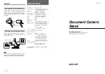
Verify planned equipment location is

 a solid, level, and structurally sound surface and 

meets the following dimensions criteria:

MODELS:

3103XX 

8-foot ceiling 

3104XX 

9-foot ceiling

3103XX model

3105XX model

3105XX Long Base 

8-foot ceiling 

3106XX Long Base 

9-foot ceiling

72 inches

(1,829 mm)

Sides*

48 inches

(1,219 mm)

Front

12 inches

(305 mm)

Rear

*Multiple Racks may share side Free Space.

Содержание 3103XX

Страница 1: ...s for future reference Skill level Professional installation is required by qualified personnel Product failure due to improper installation is not covered under warranty READ CAREFULLY KEEP THESE INS...

Страница 2: ...559 256 8000 service keiser com keiser com support After assembly please record the serial number in the space provided below Extra lines provided for multiple units Serial Nos RECORD YOUR SERIAL NUMB...

Страница 3: ...and could result in serious injury 12 KeiserCorporationisnotresponsiblefordamageorserious injury caused by incorrect installation assembly or use 13 UseoftheHalfRackoranypurposenotexplicitlyspecified...

Страница 4: ...804 mm 71 in 1 804 mm 61 in 1 550 mm 666 lbs 302 kg 61 in 1 550 mm 104 in 2 642 mm 713 lbs 324kg 92 in 2 337mm 71 in 1 804 mm 71 in 1 804 mm 93 in 2 362 mm 93 in 2 362 mm 724 lbs 329 kg 104 in 2 642...

Страница 5: ...FREE SPACE Footprint DxW 61 in x 71 in 1 550 mm x 1 804 mm Footprint DxW 93 in x 71 in 2 362 mm x 1 804 mm Footprint DxW 98 in x 71 in 2 489 mm x 1 804 mm Footprint DxW 172 in x 100 in 4 369 mm x 2 54...

Страница 6: ...time use only Covered floors wood carpet rubber etc cut out the floor mount plate pattern to mount equipment directly onto concrete Ensure equipment makes full contact with the concrete floor no gaps...

Страница 7: ...OlympicLiftingInsertandInsertPlatforms includingoptionalaccessories notshown Checkforanydamageormissing parts Ifpartsaredamagedormissing contactyourlocaldealer distributor orKeiserCustomerSupportbytel...

Страница 8: ...ssfully completed UNPACKING Position the shipping crate in a cleared area Open crate to expose the equipment as shown in Figure 5 Remove all parts from the crate by releasing all cable ties shipping m...

Страница 9: ...equipment parts help is required to safely and successfully complete the assembly procedure HEAVY OBJECT Help is required during lifting to avoid muscle strain or back injury RIGHT LEFT REAR FRONT x4...

Страница 10: ...press Foot Pedal as you begin to position the Power Module on the Base Plate Release the Foot Pedal before the Actuator Tab enters the Power Module pull the wire and air lines through the Bottom Frame...

Страница 11: ...ough the release ring button and grab ring into the fitting 3 Push the tube firmly through the O ring until it bottoms on the tube stop then pull back 4 To disconnect push the tube into the fitting ho...

Страница 12: ...e Cable Tray Tabs push any excess lines back into the Bottom Frames Tilt a Power Module with Bottom Frame for clearance to position and install the Bench Positioner B Bench Positioner Cable Tray Tabs...

Страница 13: ...s face inward Repeat the process for the Left Post NOTE There is no Communication Wire connection at the Left Post RIGHT POST with COMMUNICATION WIRE LEFT POST RIGHT POWER MODULE IMPORTANT DO NOT TIGH...

Страница 14: ...T THE BASE OF THE POSTS ARE NOT FULLY TIGHTENED TO ALLOW FOR EASY BOLT HOLE ALIGNMENT IMPORTANT DO NOT TIGHTEN BOLTS TO ALLOW FOR EASY BOLT HOLE ALIGNMENT Connect and install the Top Power Display Che...

Страница 15: ...ACK HALF RACK LONG BASE ASSEMBLY INSTRUCTIONS 15 7 INSTALL WEIGHT STACK IMPORTANT BEFORE INSTALLATION CHECK BOLTS AT ALL POST CONNECTION POINTS ARE NOT FULLY TIGHTENED TO ALLOW FOR EASY BOLT HOLE ALIG...

Страница 16: ...Catch Cantilever Spotting Bar Left side shown Set the right side components to corresponding position setting NOTE eChip Extension Strap and Weight Stack Decal sets are packaged in a kit attached to...

Страница 17: ...er Air Compressor manuals are available at keiser com support search Air Compressor manuals 1 Make sure the Half Rack has been installed according to the instructions and check all bolts are properly...

Страница 18: ...HALF RACK HALF RACK LONG BASE ASSEMBLY INSTRUCTIONS 18 This page intentionally left blank...

Страница 19: ...HALF RACK HALF RACK LONG BASE ASSEMBLY INSTRUCTIONS 19 This page intentionally left blank...

Страница 20: ...oducts referred to in this publication are trademarks of Keiser Corporation Copyright 2020 Keiser Corporation All rights reserved Distributionandcopyingofthisdocument useandcommunicationofitscontentsi...

Отзывы: