manualshive.com logo in svg
background image

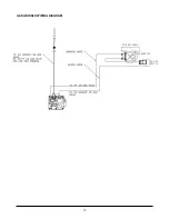
GAS CONNECTIONS AND PIPE SIZE

The Miraclean

®

Griddle requires a standard gas pipe

size of 3/4 inch (19mm) I.D. connection. The size of the
gas supply pipe is very important if the pipe is too small
you will have low gas pressure at the Miraclean

®

Griddle manifold. Low gas pressure will cause slow
recovery and/or delayed ignition. If you have a question
about gas pipe size call your local gas company.

Before connecting new pipe to the Miraclean

®

Griddle

the pipe must be blown out to remove all foreign
particles. These particles in the controls or burners may
cause improper or dangerous operating conditions.

Pipe joint compounds that are used on threaded joints
of appliance piping shall be resistant to the action of
liquified petroleum gases. When using pipe joint
compound do not apply to the first two threads. Use
only very small amount and only on male threads. This
will prevent clogging of burner orifices and the gas
valve. Never use compound on female threads as it
might be pushed into the gas valve.
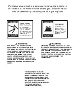
Have your installer check for gas leaks using a soap
and water solution before operating. DO NOT USE AN
OPEN FLAME TO CHECK FOR GAS LEAKS.
1) The Miraclean

®

Griddle and its individual shut off

valves must be disconnected from the gas supply
piping system during any pressure  testing of that
system at test pressures in excess of 1/2 psi (3.45kPa)
(13.84 in WC) High pressure can damage the gas

valve causing a hazardous condition.
2.) The appliance must be isolated
from the gas supply piping system by
closing its individual manual shutoff
valve during any pressure testing of
the gas supply piping system at test
pressures equal to or less than 1/2 psi
(3.45 kPa). 
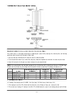
The required gas pressure for proper
operation of each Miraclean

®

Griddle

is 4" water column for natural gas and 10" water
column for propane gas at the manifold.
If more than one gas unit is on the same supply line,
you may require a larger line. Consult your local gas
company to assure adequate volume and pressure.
Refer to serial plate for proper gas requirement for your
particular model.

FLEXIBLE GAS CONNECTORS AND QUICK

DISCONNECT DEVICES

For an appliance equipped with casters:
The installation shall be made with a connector that
complies with the Standard for Connectors for Movable
Gas Appliances, ANSI Z21.69 or the Standard for
Connectors for Moveable Gas Appliances, CAN/CGA-
1.16, and a quick disconnect device that complies with
the Standard for Quick-Disconnect Devices for Use
With Gas Fuel, ANSI Z21.41 or the Standard for Quick
Disconnect devices for Use with Gas Fuel, CAN1-6.9. 
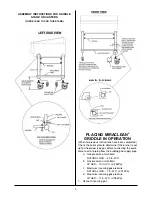
RESTRAINING DEVICES

Adequate means must be provided to
limit the movement of the appliance
without depending on the connector
and the quick-disconnect device or its
associated piping to limit the
appliance movement.
Griddle installation on stands with
caster, casters and jam nuts must be
completely tightened.
The restraint means must be attached

to the rear of the Miraclean

®

Griddle within 2" of the

center line and approximately 1-5/8" from the bottom of
the cabinet back to allow the restraining bolt to be
anchored to the cabinet back between the cabinet
bottom and inner liner to ensure positive support to
restrain Miraclean

®

Griddle movement and not depend

on the flexible gas connector, quick-disconnect or
piping to limit the Miraclean

®

Griddle movement.

If disconnection of the restraint is necessary, it must be
reconnected when the Miraclean

®

Griddle is returned to

its originally installed position.
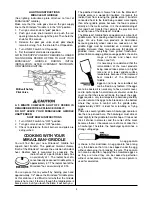
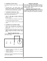
LEVELING

The Miraclean

®

Griddle will operate at its highest

efficiency when properly leveled. Place a level on the
Miraclean

®

Griddle plate from side to side. For griddles

on legs, the bottom foot of the leg is adjustable. Turn
counterclockwise to decrease height, or clockwise to
increase height until level. For griddles on stands with
casters, the casters are adjustable by loosening the
jam nut. When the desired level is reached, tighten the
jam nut. Adjustments of more than 3/4" are not
recommended on any caster. The same procedure
should be followed to level the Miraclean

®

Griddle from

front to back.

2

WARNING

Do not use

open flame

to check for leaks.

WARNING

Restraining devices

required.

Содержание MIRACLEAN Miraclean 2000

Страница 1: ...lation Instructions 1 Damage in Shipment 1 Positioning 1 Ventilation 1 National Code Requirements 1 Gas Connections and Pipe Size 2 Flexible Gas Connections Quick Disconnect Devices 2 Leveling 2 Stand Assembly 3 Lighting Instructions 4 Shutdown 4 Cooking 4 5 Cleaning 6 Preventative Maintenance 7 Avoid Service Checklist 7 Cleaning Care Conditioning 7 Thermostat Calibration 7 Service Parts Ordering ...

Страница 2: ...UALLY LOSE ITS ODOR AND PRECAUTIONS SHOULD BE TAKEN TO ASSURE THAT PROPANE GAS IS NOT PRESENT EVEN THOUGH YOU DO NOT DETECT AN ODOR IF THERE IS ANY DOUBT YOU SHOULD CALL YOUR LOCAL PROPANE GAS SUPPLIER FOR ASSISTANCE FOR YOUR SAFETY Do not store or use gasoline or other flammable vapors or liquids in the vicinity of this or any other appliance Purchaser should post in a prominent location instruct...

Страница 3: ...T RETURN DAMAGED MERCHANDISE TO KEATING FILE YOUR CLAIM AS ABOVE FIRST STEPS POSITIONING Keep appliance area free and clear of any combustibles Position the Miraclean Griddle 6 inches 152mm from any combustible material A minimum of 24 inches 610mm should be provided at the front of the Miraclean Griddle for servicing and proper operation Air for combustion enters the Miraclean Griddle from the bo...

Страница 4: ...sure Refer to serial plate for proper gas requirement for your particular model FLEXIBLE GAS CONNECTORS AND QUICK DISCONNECT DEVICES For an appliance equipped with casters The installation shall be made with a connector that complies with the Standard for Connectors for Movable Gas Appliances ANSI Z21 69 or the Standard for Connectors for Moveable Gas Appliances CAN CGA 1 16 and a quick disconnect...

Страница 5: ...ate to determine if the burner is set up for the proper type gas before connecting the quick disconnect or piping from the building gas supply pipe a Gas pressure at manifold NATURAL GAS 4 0 in W C b Gas pressure at manifold LP GAS 10 in W C 2 49kPa c Maximum incoming gas pressure NATURAL GAS 7 in W C 2 01kPa d Maximum incoming gas pressure LP GAS 11 in W C 2 98kPa 1 Connect incoming gas 3 ...

Страница 6: ...e food being cooked more rapidly than other griddle plates because the food is placed directly on the metal surface It is the understanding of this rapid heat transfer that permits the practical and beneficial use of the Miraclean Griddle The Miraclean Griddle finds an application in all sorts of griddle work from cooking wheat cakes to scrambling eggs We use these two products as illustrations be...

Страница 7: ...nventional griddles at least start at lower temperatures You may be able to work the temperature up as you become accustomed to the more rapid cooking of the Miraclean Griddle 2 Cook as usual but after each batch scrape the griddle in the work area completely clean using the 4 wide scraper supplied by Keating This may be the only cleaning you will ever need HIGH TEMPERATURE Since the Miraclean Gri...

Страница 8: ...an surface is very hard With proper care the MIRACLEAN surface and its unique cooking properties will last for many years Damage done to the Miraclean surface is irreplacable NEVER USE A GRIDDLE STONE BRICK OR SCREEN TO CLEAN THE MIRACLEAN SURFACE DAMAGE DONE TO THE MIRACLEAN SURFACE BY GRIDDLE STONE BRICK OR SCREEN WILL VOID THE WARRANTY DO NOT HACK CHOP HIT OR CUT ON THE MIRACLEAN SURFACE YOU WI...

Страница 9: ...s a thin layer of chrome oxide which acts as a releasing agent for food product You may feel that you need to recondition your griddle surface 1 Follow cleaning instructions on page 5 2 Heat the MIRACLEAN to 400 F for one hour 3 Lower thermostat to 350 F allowing the MIRACLEAN to cool to about 350 F as is evident when griddle cycles on or surface thermometer indicates correct temperature 4 Lightly...

Страница 10: ...ET ELBOW 1 2 004194 14 ORIFICE HOLDER ASSEMBLY REFERENCE ONLY 15 FITTING 1 2 NPT MALE 000615 16 BURNER TUBE 1 2 X 9 1 800 KEATING 17 ELBOW 1 2 x 3 8 006477 18 GAS VALVE MILLIVOLT NATURAL GAS 023625 PROPANE GAS 023624 Figure 6 2 ITEM DESCRIPTION P N 1 CONTRON PANEL FRAME 1 800 KEATING 2 GREASE DRAWER 30 36 Deep 052505 3 SWITCH ROCKER 035030 4 SPARK IGNITER WITH ELECTRODE NO BRACKET 008327 5 CONTROL...

Страница 11: ... is in pilot position c Thermostat is not turned on d Low gas presssure e Gas valve failure a Put ON OFF switch to ON position b Turn knob to ON position c Turn thermostat to desired temperature d Set manifold pressure to 4 WC nat 10 WC LP e Replace valve Temperature of griddle erratic a Thermostat is not calibrated b Air from exhaust hood excessive a Calibrate thermostat with exhaust system runni...

Страница 12: ...NT 1 Lower the control panel by removing the screws 2 Disconnect the wires on the switch and remove switch 3 Snap the new switch into place and reconnect all wires 4 Return the control panel to its normal position THERMOSTAT REMOVAL AND REPLACEMENT 1 Lower the control panel by removing the mounting screws 2 Locate the bulb end of the thermostat and using a wrench loosen the front and rear bolts ho...

Страница 13: ...r having a 1 1000MV range Conduct each check below by connecting meter test leads to terminals as indicated All readings are closed circuit A BURNER COIL CHECK A Reading Thermostat contacts CLOSED Gas Valve knob ON Main burner should come ON 1 If the reading is more than 100 millivolts and the automatic valve still does not come one replace the valve 2 If the closed circuit reading A reading is le...

Страница 14: ...pilot position until maximum output is observed Then extinguish pilot and observe meter 2 Dropout of automatic pilot magnet sound should be audible should occur between 75 millivolts and 25 millivolts If dropout occurs outside these limits change the valve MILLIVOLT CONTROL VALVE To check Resistance of the gas valve connect one wire to the valve as shown 1 Resistance between the THTP TH terminals ...

Страница 15: ...13 GAS GRIDDLE WIRING DIAGRAM CONTROL PANEL THERMOSTAT ON OFF SWITCH ...

Страница 16: ...NTY AGAINST LATENT DEFECTS E XCLUSIONS The warranties provided by Keating of Chicago Inc do not apply in the following instances 1 Defects arising out of or resulting from improper installation or maintenance abuse misuse modification or alteration by unauthorized service personnel or any other condition not attributable to a defect in material or workmanship Proper installation and maintenance ar...

Страница 17: ...____________________________________________________ ADDRESS __________________________________________________________________________________________________________________ CITY ______________________________________________________________________________ STATE ________________ ZIP ____________ DEALER _____________________________________________________________________________________________...

Отзывы: