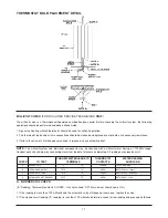
B. THERMOPILE OUTPUT CHECK
(“B” Reading. Thermostat contacts OPEN - Main burner
OFF.)
1. Thermopile system - 500 millivolts minimum. If the
minimum millivolt reading is not obtainable, readjust
thermopile for maximum millivolt output. If millivolt reading
is still below minimum specified, replace thermopile.
C. THERMOSTAT RESISTANCE CHECK
(“C” Reading. Thermostat contacts CLOSED - Gas valve
knob “ON”. Main burner should be ON.)
1. If the “C” reading drops more than 80 millivolts, the
resistance in the system is excessive and must be
reduced. To correct:
a. Clean and tighten thermostat leads and connections.
b. Shorten or replace theirmostat lead wires.
c. Cycle thermostat rapidly (manually turn dial) to clean
contacts.
D. AUTOMATIC PILOT DROPOUT CHECK
1. Hold gas valve knob depressed in pilot position until
maximum output is observed. Then extinguish pilot and
observe meter.
2. Dropout of automatic pilot magnet (sound should be
audible) should occur between 75 millivolts and 25
millivolts. If dropout occurs outside these limits, change
the valve.
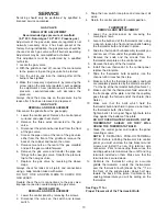
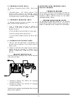
MILLIVOLT CONTROL VALVE
To check Resistance of the gas valve, connect one wire
to the valve as shown.
1.
Resistance between the THTP & TH terminals
must be 11.5
⍀
±0.2
⍀
2.
Resistance between the THTP & TP terminals
must be 10.0
⍀
±0.2
⍀
If resistance is outside of specifications listed, the gas
valve must be replaced.
BEFORE REPLACING THERMOPILE CHECK
MILLIVOLT READINGS
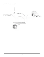
THERMOPILE READINGS
With all wires connected, with the pilot on and burners
off, the thermopile reading at the TP&THTP terminals
should be ~500mv. With the burners on, the millvolt
reading should be ~200mv.
WARNING AND OPERATING PLATES
All warning and operating plates on the Keating
MIRACLEAN
®
Griddle should be in place at all times. If
plates are damaged or lost, replace them immediately.
12

