background image

KE 4256-5492 Keatec T Series 10-20kVA PF1.0 208Vac with Internal Battery 7.0 Touch Screen Users Guide English 20181118 

This manual is for qualified personnel only     


Page  17 


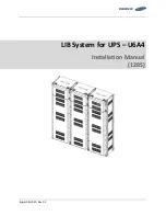
T SERIES UPS battery connection   


3.10


UPS Parallel Installation


The following sections introduce the installation procedures specific to a parallel system. 


3.10.1


Cabinet installation 


Connect all the UPS needed in the parallel system as below. 


Make sure each UPS input breaker is in the “off” position and there is no output from any of the UPS.   

Battery groups can be connected separately or in parallel, which means the system can be either a 

separate battery or a common battery.     


WARNING! 

Make certain the N, A (L1), B (L2), C (L3) lines are correct and grounding is well 

secured.   


3.10.2


Parallel cable installation 

The  shielded  and  double  insulated  control  cables  must  be  interconnected  in  a  ring  configuration 

between UPS units as shown below. The ring configuration ensures high reliability of the control. 


Содержание T SERIES

Страница 1: ...OR OTHER DOCUMENTATION B ASSUMES NO RESPONSIBILITY OR LIABILITY FOR LOSSES DAMAGES COSTS OR EXPENSES WHETHER SPECIAL DIRECT INDIRECT CONSEQUENTIAL OR INCIDENTAL WHICH MIGHT ARISE OUT OF THE USE OF SU...

Страница 2: ...ces 10 3 6 Power Cables 10 3 7 Power cable connections 11 3 8 Internal Battery Connection 14 3 9 External Battery Connection 15 3 10 UPS Parallel Installation 17 3 11 Computer access 18 4 Operation 19...

Страница 3: ...when the input AC power is disconnected WARNING No User serviceable Parts Risk of electrical shock do not remove cover No user serviceable parts inside Refer servicing to qualified service personnel...

Страница 4: ...source from ground WARNING Contact with any part of a grounded battery can result in electrical shock The likelihood of such shock can be reduced if groundings are removed during installation and mai...

Страница 5: ...enhances and increases reliability performance self protection self diagnostics and so on Charging Current is configurable Using the PC Software the user may set the capacity of the batteries as well...

Страница 6: ...acceptance file a claim for concealed damage with the carrier Unpacking the UPS in a low temperature environment may cause condensation to occur inside the UPS enclosure To reduce the hazard of electr...

Страница 7: ...6 5492 Keatec T Series 10 20kVA PF1 0 208Vac with Internal Battery 7 0 Touch Screen Users Guide English 20181118 This manual is for qualified personnel only Page 6 3 2 Cabinet Overview Front View Side...

Страница 8: ...ver 1 LCD panel LEDs 2 Intelligent Slot 1 SNMP card Relay card 3 Intelligent Slot 2 SNMP card Relay card 4 Dry contact port 5 Power Switch 6 USB port 7 RS485 port 8 RS232 port 9 O P Switch 10 Maintena...

Страница 9: ...cover 1 LCD panel LEDs 2 Intelligent Slot 1 SNMP card Relay card 3 Intelligent Slot 2 SNMP card Relay card 4 Dry contact port 5 Power Switch 6 USB port 7 RS485 port 8 RS232 port 9 O P Switch 10 Mainte...

Страница 10: ...hould be installed Air filters should be used to prevent from dust entering the UPS The environment temperature around the UPS should in the range of 0 40 C If the environment temperature exceeds 40 C...

Страница 11: ...over current through a DC compatible thermo magnetic circuit breaker or a set of fuses located close to the battery UPS Output Any external distribution board used for load distribution shall be fitt...

Страница 12: ...able Connect each cabinet to the main ground system For Grounding connection follow the shortest route possible WARNING Failure to follow adequate earthing procedures may result in electromagnetic int...

Страница 13: ...ine IN OUT Input Output Output L1 Output Phase L1 Input L1 Primary input Phase L1 Output L2 Output Phase L2 Input L2 Primary input Phase L2 Output L3 Output Phase L3 Input L3 Primary input Phase L3 Ou...

Страница 14: ...put N Input Neutral for primary and secondary input GND Grounding Bps L1 Secondary input Phase L1 BAT Positive terminal of the battery string Bps L2 Secondary input Phase L2 BATN Neutral terminal of t...

Страница 15: ...the equipment below the power connections All cabinets in the UPS must be grounded properly CAUTION The earthing and neutral bonding arrangement must be in accordance with local and national codes of...

Страница 16: ...tteries installation 3 9 External Battery Connection The UPS adopts positive and negative double battery framework with 20pcs in series A neutral cable is retrieved from the joint between the cathode...

Страница 17: ...settings can be done through LCD panel or monitoring software CAUTION Ensure correct polarity battery string series connections I e inter tier and inter block connections are from to terminals Do not...

Страница 18: ...n the parallel system as below Make sure each UPS input breaker is in the off position and there is no output from any of the UPS Battery groups can be connected separately or in parallel which means...

Страница 19: ...ll the UPS modules must be connected to a common output bus 4 The length and specification of power cables including the bypass input cables and the UPS output cables must be the same This facilitates...

Страница 20: ...nverter before using the PC Software to set the output voltage and frequency 4 Operation 4 1 Operation Modes The UPS is a double conversion on line UPS that may operate in the following modes Normal m...

Страница 21: ...of unsynchronized AC sources This interruption is programmable but typically set to be less than an electrical cycle e g less than 15ms 50Hz or less than 13 33ms 60Hz ECO Mode When the UPS is at AC M...

Страница 22: ...up after 4 Switch ON UPS output switch If the rectifier fails at start up the bypass LED will light up When the inverter starts up the UPS will transfer from bypass mode to inverter mode and then the...

Страница 23: ...ill supply to the load through the MAINTENANCE breaker Switching to normal operation from mechanical bypass CAUTION Do not attempt to switch the UPS back to normal operation until it has been verified...

Страница 24: ...there should be no output On line mode 1 Press OFF to shut down the UPS wait about 30s 2 Open the BATTERY breaker 3 Open the battery power switch for standard UPS 4 Switch to OFF the AC input breaker...

Страница 25: ...24 4 2 6 Parallel Settings 1 Connect the UPS to the computer 2 Power on the UPS 3 Open Muser4000 software click System then select User Set 4 From User Set window click Set 5 From the Data Set window...

Страница 26: ...ow select Ups ID and put the ID value for the parallel UPS in the box on the right side Click Set to save the values as shown below The UPS will sound a beep to indicate that the setting has been corr...

Страница 27: ...setting 4 Turn off the input breaker of Unit 1 and make sure the UPS is off Turn on the input breaker of Unit 2 access the LCD setting interface setting the parallel working mode ID NO 2 parallel 4 u...

Страница 28: ...he UPS by flow chart Touch the bypass icon to enter the bypass data window touch the back icon return to last window and touch the homepage icon jump to main page Touch the mains icon to enter the mai...

Страница 29: ...nternal Battery 7 0 Touch Screen Users Guide English 20181118 This manual is for qualified personnel only Page 28 Touch the battery icon to enter the battery data window touch the back icon return to...

Страница 30: ...personnel only Page 29 4 3 2 Run Info From the Home page touch the Run info icon to enter the information page Touch the Status Information icon to enter the status data window click the back icon ret...

Страница 31: ...ata window touch on the back icon return to last window and touch on the homepage icon jump to main page Touch the history icon to enter the history window can see the history data touch the back icon...

Страница 32: ...for qualified personnel only Page 31 4 3 5 Maintenance Touch Maintenance icon to enter setting page touch the back icon return to last window and touch the homepage icon jump to main page 4 3 6 Functi...

Страница 33: ...GUISH 12 Fault Mode LIGHT X X X CAUTION X means it is determined by other conditions Alarm Information Fault code Err UPS Alarm Warning Buzzer LED 1 Rectifier Fault Beep continuously Fault LED lit 2 I...

Страница 34: ...second Fault LED blinking 30 Rectifier over current Once per second Fault LED blinking 31 Bypass over current Once per second BPS LED blinking 32 Overload Once per second INV or BPS LED blinking 33 N...

Страница 35: ...PP function to enable the remote control via the internet when the network is unavailable In addition to the features of a standard NetAgent Mini NetAgent II has the option to add NetFeeler Lite to de...

Страница 36: ...25 of nominal output current IEC 60947 2 curve C Current rating of neutral cable A 1 7 In Generator Input Support OUTPUT Inverter Output Power factor 1 0 Rated AC Voltage 1 208 120Vac or 220 127Vac 50...

Страница 37: ...sfer Asynchronous transfer 15ms 50 Hz 13 3ms 60 Hz Alarms overload utility abnormal UPS fault battery low etc Protection short circuit overload over temperature battery low fan fault alarm Communicati...

Страница 38: ...ure the output cable is well connected Switch ON output breaker 4 Utility LED is flashing Utility voltage exceeds UPS input range If the UPS operates in battery mode pay attention to the remaining bac...

Страница 39: ...SB port PC USB port UPS USB port Description Pin 1 Pin 1 PC 5V Pin 2 Pin 2 PC DPLUS signal Pin 3 Pin 3 PC DMINUS signal Pin 4 Pin 4 Signal ground Available function of USB Monitor UPS power status Mon...

Страница 40: ...rt and UPS RS232 port PC RS232 port UPS RS232 port Pin 2 Pin 2 UPS send PC receive Pin 3 Pin 3 PC send UPS receive Pin 5 Pin 5 ground Available function of RS232 Monitor UPS power status Monitor UPS a...

Страница 41: ...Pin 1 5 485 A Pin 2 4 Pin 2 4 485 B Pin7 Pin7 12Vdc Pin8 Pin8 GND Available function of RS485 Monitor UPS power status Monitor UPS alarm info Monitor UPS running parameters Timing off on setting Batte...

Страница 42: ...ion Pin 1 5 Pin 1 5 485 A Pin 2 4 Pin 2 4 485 B Pin7 Pin7 12Vdc Pin8 Pin8 GND Available function of BAT_T Battery environment temperature monitoring Charging voltage modulation depending on batteries...

Страница 43: ...ction diagram Connection between the button and UPS REPO port Button UPS REPO Description Pin 1 Pin 1 EPO Pin 2 Pin 2 GND A remote emergency stop switch Dry contact signal and normally open not provid...

Отзывы: