


© Copyright 2015 KE2 Therm Solutions, Inc., Washington, Missouri 63090
Q.1.3 July 2015
Page 11
KE2
Evaporator
Efficiency
Quick Start Guide
Evaporator wiring – Auxiliary
The auxiliary relay is optional and wiring will vary depending on the
auxiliary relay method selected.
Depending on auxiliary relay location, an additional conduit may
be required.
Strip the ends selected to control the auxiliary component.
Break the hot leg of the auxiliary component.
Attach the wire from the NO terminal on the auxiliary relay to one
of the auxiliary component leads. Attach the wire from the COM on
the auxiliary component relay to the L1/Line Voltage.
Connect L2/Neutral to the remaining auxiliary component lead.
Route and secure the conduit to the location the controller is to be
installed.
Wiring must follow local wiring codes.
22
22
Installing the sensors
Although not required, sensors should be labeled with their func-
tion. This will eliminate confusion when connecting the sensors to
the controller.
Air Sensor Bracket
Install the Air Temperature Sensor using the Stainless Steel self-
piercing screw and bracket from the accessory kit.
The end with the single loop is designed to be mounted with the
screw included.
The end with multiple loops is designed to hold the sensor.
Locate the best place to install the sensor.
The sensor should be located between 8 - 10 inches away from
the face of the evaporator. This distance prevents the sensor from
sensing heat from the heating elements during the defrost cycle, but
close enough to accurately sense the return air temperature.
The sensor bracket may be bent as necessary to locate the sensor
in the proper position.
WARNING!
Do not allow the metal portion of the air sensor to touch any-
thing other than air. It should not touch the bracket, nylon cable
tie, or any other solid surface.
23
23
21
Coil Sensor
The coil sensor location is of the utmost importance for the
proper operation of the controller. It is essential that the sen-
sor is in the coldest location on the coil at the end of the defrost
cycle, to ensure a complete defrost. See preliminary steps A-D on
page 3 to determine the coldest location on the coil.
Once you determine the proper sensor location, as described in pre-
liminary steps A-D on page 3, the sensor can be installed.
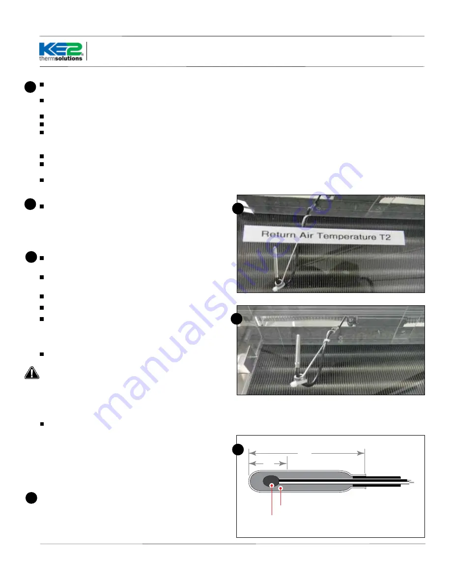
1.5”
Thermistor
Epoxy
.5”
24
Installing the Sensor Properly
Note, the most active portion of the sensor is the first 1/2” of the
1-1/2” long stainless steel probe. Figures 25 and 26 show two meth-
ods for installing the sensor in the coil. The method shown in 25 will
work in most applications, however in some cases inserting the sen-
sor into the coil may position it too close to the defrost heat source. In
these instances, the method shown in Figure 26 can be used.
24