background image

Page. 2

   PROPER OPERATION 

Please use the replacement of parts on the manual to ensure the safety of instructors.


This product is for R/C model, so do not use for other purpose.

   SAFE OPERATION 

Operate this unit within your ability. Do not fly under tired condition or improper operation, which may cause danger.

3.Safety Check Before Flying

Before flying, for safety reasons, make sure that no one else is operating a R/C model on the same frequency as yours.
Before flying, please check that the power of your transmitter and your helicopter are sufficient for the flight.
Before turning on the transmitter, please check that the throttle stick is in its lowest position, IDLE UP switch must be on OFF position.
When turning off the model, please follow the power on/off procedure. Power ON: turn on the transmitter first, then turn on
helicopter power. Power OFF: turn off the helicopter power first and then turn off the transmitter. Improper operating procedure
may cause the model to be out of control, so please do make this your habit.
Before operation, check that every movement is smooth and directions are correct. Inspect servos carefully for interferences and broken gears.
Check for missing or loose screws and nuts. See if there is any cracked and/or incomplete assembly of parts.
Check main rotor blades and rotor holders carefully. Broken and premature failures of parts might result in a dangerous situation or crash.
Check all ball links to avoid excess play and replace as needed. Failure to do so will result in poor flight stability.
Check that the battery and power plugs are fastened. Vibrations and violent flight might loosen the plugs and so lead to out of control.
Check for the tension of main drive belt.

   PREVENT MOISTURE

R/C models are composed of many precision electrical components. lt is critical to keep the model and associated equipment away from moisture and other contaminants. 
The introduction or exposure to water or moisture in any form can cause the model to malfunction resulting in loss of use, or a crash. Do not operate or expose to rain or 
moisture.

   KEEP AWAY FROM HEAT 

R/C models are made up of various forms of plastic. Plastic is very susceptible to damage or deformation due to extreme heat and cold climate. Make sure not to store the 
model near any source of heat such as an oven, or heater. lt is best to store the model indoors, in a climate-controlled, room temperature environment.

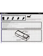
4.Tools Required

-Hex drivers : 1.5, 2, 2.5, 3, 4mm
-Nut Drivers : 2, 4, 7mm
-Ball link pliers
-Diagonal cutting pliers
-Scissors
-Metric ruler
-Soldering iron + solder (for motor and ESC wiring)
-Pitch gauge (for set up)

-Swashplate leveller
-Threadlock blue * (medium)
-Threadlock red * (high strength)
-Bearing retainer compound
-Epoxy A+B Glue
-Grease
-Oil
*Colors may vary depending on your area.

Содержание Chase 360

Страница 1: ...nk you for buying Chase products Please read this manual carefully before assembling We recommend that you keep this manual for future reference regarding tuning and maintenance INSTRUCTION MANUAL INS...

Страница 2: ...k of danger Apply thread lock as indicated allow the threadlock to cure before mounting parts It is recommended to use threadlock on each bolt or screw that are engaged with metal parts LOCATE AN APPR...

Страница 3: ...rotor blades and rotor holders carefully Broken and premature failures of parts might result in a dangerous situation or crash Check all ball links to avoid excess play and replace as needed Failure t...

Страница 4: ...or blades 6 channel or more helicopter transmitter system 2 4 Ghz frequency preferred Receiver 6 channel or more working with your transmitter specs A Glue width approx 2mm 2mm OIL Lubrication grease...

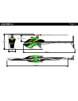
Страница 5: ...200mm 688mm 90mm Centre of Gravity 96mm 814mm Page 4...

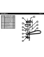
Страница 6: ...nion 1ST Stage pulley pin 2 3 4 5 6 7 8 9 10 11 ITEM NO DESCRIP TION QTY 1 1 2 8 3 1 4 1 5 1 6 1 7 2 8 9 10 11 1 1 1 1 Round head screw M2 5 x 6 Bearing 4x10x4 Motor mount bracket right Motor mount br...

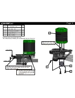
Страница 7: ...und on the shaft for the pinion grub screw This step can be completed at any time But is easier before installing the 1st stage assembly into the model 2 1 3 4 Set Screw M3 Flat head screw M3X6 Motor...

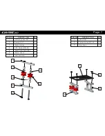
Страница 8: ...her GYRO TRAY Boom Clamp 1 2 4 6 3 7 1 2 3 4 5 ITEM NO DESCRIP TION QTY 1 1 2 4 3 2 4 2 5 1 6 4 7 2 ITEM NO DESCRIP TION QTY 1 1 2 4 3 2 CAP Screw M3 x 24 UP Pulley holder SET Spacer sleeve Down Pulle...

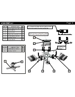
Страница 9: ...wise CYCLIC SERVO Lock Nut M2 UPPER BEARING BLOCK Bearing 8x16x5 SERVO MOUNT LOWER BEARING BLOCK 1 2 3 4 5 6 7 1 2 ITEM NO DESCRIP TION QTY 1 6 2 3 3 6 4 6 5 4 6 1 7 3 ITEM NO DESCRIP TION QTY 1 1 2 1...

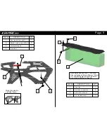
Страница 10: ...option Refer to Step 26 Mirror this step for Left side frame Lipo tray button right Side frame LIPO 1200 1400mAh 1 2 4 3 1 2 4 3 Round head screw M2 x 4 ITEM NO DESCRIP TION QTY 1 1 2 3 3 1 4 1 canop...

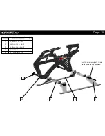
Страница 11: ...O DESCRIP TION QTY 1 LANDING GEAR LEFT 1 2 LANDING GEAR RIGHT 1 3 LANDING GEAR MOUNT 2 4 FROM STEP 6 1 5 8 lock the screws only after main frame left is well assembled 1 2 3 4 5 CAP Screw M2 5 x 10 Pa...

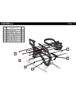
Страница 12: ...FRAME SPACERS 2 Lipo sliding rail right 1 Round head screw M2 x 4 2 2 CAP Screw M2 5 x 6 5 1 2 3 ITEM NO DESCRIP TION QTY 1 2 3 4 5 4 5 CAP Screw M2 5 x 8 6 Frame Washer Red 7 6 Page 11...

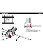
Страница 13: ...in the tail shaft by fastening the Locking collar and pinion against the bearings Tail shaft Tail shaft locking collar Tail Pinion 15T Set Screw M3x3 Tail Box Bearings 4x8x3 1 1 2 1 1 2 ITEM NO DESCR...

Страница 14: ...ils ITEM NO DESCRIP TION QTY 1 Fin Spacer 1 2 Tail Boom 1 3 2 4 Pitch Slider Bracket 1 5 Tail Belt 1 6 1 7 1 8 1 9 Tail control guide 2 10 1 11 1 11 1 2 3 4 5 8 7 6 10 9 12 12 2 CAP Screw M2 x 10 CAP...

Страница 15: ...ITEM NO DESCRIP TION QTY 1 Parts From Step 4 1 2 Tail Belt 1 3 Parts from Step 10 1 4 Boom Clamp 1 1 2 3 4 Page 14...

Страница 16: ...NO DESCRIP TION QTY 1 Parts From Step 5 1 2 Parts From Step 10 1 3 5 ITEM NO DESCRIP TION QTY 1 Front canopy mounting bolt 1 2 1 1 2 3 1 2 CAP Screw M2 5 x 6 Frame Washer Red 4 5 4 Set Screw M2 5x10...

Страница 17: ...TION QTY 1 One way bearing 10x14x6 1 2 1 3 1 4 1 5 1 6 1 ITEM NO DESCRIP TION QTY 1 Parts From Step 1 1 2 1 3 1 4 1 1 2 4 3 1 2 3 4 5 6 Bearing 8x14x4 First reduction gear 80T Bearing 10x15x4 Auto ro...

Страница 18: ...ITEM NO DESCRIP TION QTY 1 2 2 2 3 2 1 2 CAP Screw M2 5 x 6 CAP Screw M2 5 x 10 Frame Washer Red Page 17 3...

Страница 19: ...7 8 3 4 5 6 7 8 9 9 10 2 Set Screw M2 5x10 Frame Washer Red 1 Rear canopy mounting bolt CAP Screw M2 5 x 6 CAP Screw M2 5 x 8 Round head screw M2 x 4 1 Lipo sliding rail left 1 CF front electronics b...

Страница 20: ...mbled ITEM NO DESCRIP TION QTY 1 1 2 1 3 6 4 1 5 1 6 5 7 1 2 3 4 5 6 7 Oscillating bearing Swashplate Internal Linkage ball A Swashplate Outer ring Swashplate mounting pin Round head screw M2 x 4 Bear...

Страница 21: ...5 6 7 Flybarless linkage arm Flybarless swashplate control arm 6 5 7 8 9 10 11 8 2 2 2 2 Main rotor holder Bearings 5x10x4 Linkage ball A Round head screw M2 x 4 Main rotor branch control arm 2 4 2 4...

Страница 22: ...EM NO DESCRIP TION QTY 1 6 2 3 1 ITEM NO DESCRIP TION QTY 1 4 2 4 3 2 ITEM NO DESCRIP TION QTY 1 1 2 1 2 1 2 1 3 2 Ball link A Linkage rod 15mm Set Screw M2 5x10 Ball link B Linkage rod 15mm Lock Nut...

Страница 23: ...ITEM NO DESCRIP TION QTY 1 2 2 1 3 1 4 2 1 2 3 4 Round head screw M2 x 6 Anti rotation bracket 5 2 5 CAP Screw M2 5 x 6 Frame Washer Red Anti rotation bracket mount Page 22...

Страница 24: ...6 5 4 3 2 1 8 9 7 1 3 2 6 7 8 9 CAP Screw M2 x 5 ITEM NO DESCRIP TION QTY 2 1 2 2 Bearings 3x6x2 5 Thrust bearing F5 10M Tail rotor holder Linkage ball B Washer 3 1x4 4x0 3 Washer 2 1x5x0 7 Flat head...

Страница 25: ...assembled ITEM NO DESCRIP TION QTY 1 1 2 2 3 4 4 1 5 2 6 2 7 4 1 2 3 5 6 7 8 8 1 1 Tail push bearing mount Bearings 6x10x3 E clip 1 5mm T type arm Ball link for tail holder Pin Tail push bearing Set S...

Страница 26: ...ust if required 8 9 ITEM NO DESCRIP TION QTY 1 2 2 1 3 1 4 1 5 2 ITEM NO DESCRIP TION QTY 6 1 7 2 8 1 9 1 Flange Bearing 2x5x2 5 Lock Nut M2 Linkage ball A CAP Screw M2 x 4 Tail rocket arm Round head...

Страница 27: ...At the front high in the frame for 1 the lowest moment of inertia and optimal CG 2 Under the tail boom at the rear of the frame ITEM NO DESCRIP TION QTY 1 1 2 4 3 2 ITEM NO DESCRIP TION QTY 1 4 2 1 3...

Страница 28: ...Screw reserved for boom brace installation Build the tail pushrod to suit your desired servo location For rear mount servo Extension for front mount servo Page 27...

Страница 29: ...ed in multiple locations 1 2 3 4 5 6 7 ITEM NO DESCRIP TION QTY 1 2 2 4 3 4 4 2 5 1 6 1 7 2 Tail boom brace Tail boom brace end Frame Washer Red CAP Screw M2 5 x 8 CAP Screw M2 5 x 6 Tail boom brace m...

Страница 30: ...60 006 Washout control arm KC 360 005 2 x Washout control arm Main rotor holder grips KC 360 001 2 x Main rotor head Upper Motor block KC 360 012 1 x Upper Motor block 1 x Swashplate complete Complete...

Страница 31: ...C 360 045 1 x Tail Rotor Hub Tail boom support KC 360 046 2 x Tail boom support Tail rotor holder KC 360 044 1 x Tail rotor holder Tail Pitch Assembly KC 360 043 1 x Tail Pitch Assembly CF frame plate...

Страница 32: ...el gear umbrella gear 17T one way 10 14 8 KC 360 065 1 x one way Flange bearing KC 360 068 1 x Flange bearing 2 5 2 5 Flange bearing KC 360 069 1 x Flange bearing 4 8 3 Thrust bearing F5 10M KC 360 06...

Страница 33: ...14 4 Bearing KC 360 074 Bearing KC 360 075 1 x Bearing 10 15 4 Bearing KC 360 077 1 x Tall blade 62mm Tall blade 62MM KC 360 079 Bearing KC 360 076 1 x Bearing 8 16 5 Canopy KC 360 090 1 x Canopy Bear...

Страница 34: ...ntly and shorten the interval as necessary 2 One way Bearing One way bearings have longer lifetimes Failure is not common To keep the one way bearing in good operation remove it to clean and lubricate...

Страница 35: ...Version No 20150315 it s time to fly different...

Отзывы: