31
Table 2: LED Flash Sequence
Priority
Name
Flash Rate
1
Capacitor Over
Temperature
2
5
Temperature
Sensor Error
3
4
Contactor Over
Current Error
4
2
Low Capacitor
Voltage Error
6
3
Rapid Voltage
Decay after
Recharge
7
6.1 To Check MKSM Internal Circuit
1.
If the wiring and harnesses are in good order, continue troubleshooting by unplugging
the Deutsch connector on the end-faceplate of the MKSM, providing access to the pin
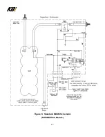
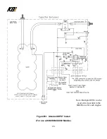
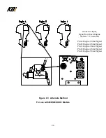
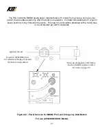
terminals on the MKSM connector. Refer Figure 5, and Figure 6.
2.
With the circuit breaker reset, use a voltmeter to check voltage at Pin #1 of the Deutsch
four-pin connector and the MKSM negative
(–)
ground power stud terminal. If voltage is
present, the circuit is good. The voltage reading is the actual KAPower module voltage
and should be at least 12-volts for the 24-volt models and 6-volts for the 12-volt models
in order to activate the contactor.
3.
Jump pins 1 and 2 on the four-pin connector, the contactor should activate and make a
“clunk” sound. If not, contact KBI for assistance.
4.
If experiencing problems check the integrity of the vehicle or vessel side of the wiring
harness for issues such as shorts, corrosion, chafing, or bad connections and
components.
5.
Check the circuit breaker and contactor relay connections within the MKSM module. In
order to service or replace any of these components, remove the cover of the MKSM
enclosure, with the assistance of KBI.
6.
The PLC Module is a sealed unit. It cannot be serviced. If additional troubleshooting is
required, contact KBI.
Содержание KAPower MKSM Series
Страница 10: ...10 Figure 2 Typical Cable Installations ...
Страница 11: ...11 Figure 3 Six 6 Cell MKSM Material Shell 16ga SS 304 2B Cover 18ga SS 304 2B Weight 21 5lb 9 75Kg ...
Страница 17: ...17 Figure 6 Standard MKSM Schematic MKSMXXX00 Models ...
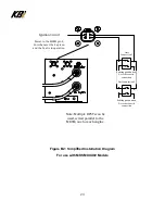
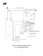
Страница 28: ...28 Figure C3 Multiple Engine MKSM Schematic For use with MKSMXXX01 Models ...

