KB Electronics PENTA KB POWER KBRG-225D Скачать руководство пользователя страница 9

7

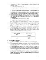
FIG. 3 – AC LINE VOLTAGE

JUMPER SETTING

FIG. 4 – MOTOR ARMATURE

VOLTAGE JUMPER SETTING

115VAC

230VAC

90VDC

180VDC

TABLE 5 – RELATIONSHIP of AC LINE INPUT AND MOTOR

VOLTAGE with J1A, J1B and J3 JUMPER POSITION

AC INPUT VOLTAGE

J1A, J1B

POSITION

J3 POSITION

MOTOR VOLTAGE

115

115

90

90

230

230

180

180

230

230

90*

90*

*A 90VDC motor can be used with a 230VAC line.  However, speed range may be reduced and
motor overheating may result.

D. J4 - Tach-generator Voltage –

 (Note:  Selection of the jumper position is not required if

armature feedback is used.)  Place J4 jumper in the position "7V", "20/30V," 

"50V"

 that

corresponds to the tach-generator voltage in Volts/KRPM. Note:  The tach voltage jumper
position is based on motor speed of 1,800 RPM.

For example, if the tach is 25V/KRPM and the motor speed is 3,600 RPM, use the "50V"
J4 position.   For other tach-generator voltages and motor speeds, an external resistor
(RT) may be used as follows.

i.

Install resistor in series with either tach-generator lead.

ii.

Place J4 in "7V" position.

iii. The value of RT is calculated as follows.

RT = [(5.4 x Vt x S) - 68,000]

VT = Tach voltage in volts/1000 RPM

Choose the closest standard  watt

S = Base Speed of motor in RPM

resistor value to the calculated value

E. J5 - Feedback Type –

 The KBRG can be operated in either armature feedback 

"AFB"

or tach-generator feedback "TFB."  Armature feedback provides adequate load regulation
for most applications.  For very precise performance, tach-generator feedback "TFB"
should be used.  (Note:  If tach feedback is desired, an external DC tach-generator must
be used and connected as per instructions.)  (See section V J, p. 12 for tach-generator
wiring.)  (Note:  The IR Comp trimpot must be set to the minimum setting [CCW] for tach
feedback.)

F. J6 - Current Limit (CL) Mode –

 The KBRG contains electronic current limiting that limits

the maximum DC current to the motor.  (Note:  Current Limit is established with the
selection of the J2 position and the setting of the Forward and Reverse CL trimpots "FWD
CL" and "REV CL.")

Содержание PENTA KB POWER KBRG-225D

Страница 1: ...5 TB1 12 9 7 8 10 11 13 J3 F1 EARTH T1 GND DB ACCEL ACCEL REV FWD RESP SPD MAX CL CL COMP IR REV FWD TCL J8 NLT S LT OFFSET R33 EN FWD REV EN ON PWR CL See Safety Warning on Page 2 The information con...

Страница 2: ...on 8 7 Field Connections 10 8 Control State vs Relay Contact State 12 9 Armature Fuse Chart 13 10 Current Limit Timer Settings 15 11 Parts List Logic Board 16 17 12 Parts List Power Board 19 FIGURES 1...

Страница 3: ...ctory set for speed control operation SPD For torque control set J7 to TRQ position Note J8 must be set to the S LT position for speed control operation 3 MOTOR CURRENT Jumper J2 is factory set for 15...

Страница 4: ...Inhibit are not isolated from AC line Be sure to follow all instructions carefully Fire and or electrocution can result due to improper use of this product This product complies with all CE directive...

Страница 5: ...3 FIG 1 CONTROL LAYOUT Illustrates Factory Setting of Jumpers and Approximate Trimpot Settings...

Страница 6: ...of the mode selected Set jumper J7 to SPD for speed control or to TRQ for torque control See fig 1 p 3 A Speed Control Mode When jumper J7 is set to the SPD position the KBRG will vary the motor spee...

Страница 7: ...er roll diameter changes The S LT torque characteristics are shown in fig 2A FIG 2A LINEAR TORQUE CURVE In the NLT position only torque not speed is varied by the input signal The motor output torque...

Страница 8: ...utput current is set to 150 of the J2 position which may be readjusted using the FWD CL and REV CL trimpots Note On Model KBRG 240D position 10A is factory setting TABLE 4 JUMPER J2 POSITION vs MOTOR...

Страница 9: ...RT may be used as follows i Install resistor in series with either tach generator lead ii Place J4 in 7V position iii The value of RT is calculated as follows RT 5 4 x Vt x S 68 000 VT Tach voltage i...

Страница 10: ...suitable for the KBRG 240D at full rating and a 12 x24 x36 enclosure is suitable for the KBRG 225D at full rating Smaller enclosures may be used if full rating is not required V WIRING Warning Read S...

Страница 11: ...LINE FUSE FUSE 2 1 3 4 6 5 12 9 7 8 10 11 13 F1 T1 R69 NOTE CONTROL SHOWN ABOVE IS MODEL KBRG 225D 10 00 203 20 254 00 8 00 25 40 7 62 1 00 0 30 DWG C3900 1 00096 180 34 7 70 7 10 195 58 3 440 87 4 4...

Страница 12: ...Voltage Field Voltage VDC Field Connection 115 90 100 F F 115 90 50 F L1 230 180 200 F F 230 180 100 F L1 230 90 100 F L1 Step down operation see sec III C p 6 D Ground Be sure to ground earth the con...

Страница 13: ...is in ENABLE state When terminals 8 and 9 are open control is in INHIBIT state See fig 9B IMPORTANT If Enable is not used a jumper must be installed between terminals 8 and 9 or control will not opera...

Страница 14: ...des require that each ungrounded conductor contain fusing Separate branch circuit fusing may be required Check local electrical codes 2 Armature Fuse An armature fuse F2 is also provided with a rating...

Страница 15: ...ment of trimpots in order to tailor control to exact requirements Readjust trimpots as follows A Forward Acceleration FWD ACCEL and Reverse Acceleration REV ACCEL The FWD ACCEL trimpot determines the...

Страница 16: ...ween forward and reverse Adjust deadband trimpot CW until the instability disappears Oscillation may also occur due to response setting See section VIII G p 15 D Forward Current Limit FWD CL and Rever...

Страница 17: ...If response is made too fast unstable operation may result H Timed Current Limit TCL Trimpot Trimpot is functional only when control is wired for 3 wire Start Stop and J6 is in the TCL position The TC...

Страница 18: ...ee expressed or implied and we are not responsible for any expense including installation and removal inconvenience or consequential damage including injury to any person caused by items of our manufa...

Отзывы: