pag.
1
9
5.2 System address and network address setting
1) After first powered on, please set the system address by remote controller or wired
controller, the address range is 0
-
63, the indoor unit addresses of the same system
can not be repeated.
2) Display as the table.5-2, when there are different ENC1, the address setting will be dif-
ferent;
Each independent control box needs to be set an address, this address is an actual
address; when the capacity code ENC1 is selected to be E-4, this indoor unit inde-
pendent control box will produce virtual address(es) with corresponding quantity based
on the set actual address, and if an address has been an actual address or virtual
address, then this address can not be the actual address or virtual address of other
indoor unit in the same system;
For example, if there are two independent control boxes in the same system, one of
the capacity code is E, the setting actual address is 5, then according to the table.7-2
this control box will produce one virtual address as 6, and then the actual address and
the virtual address of the other independent control box can not be any one of 5, 6;
The actual address and the virtual address should less than or equal to 63.
3) The indoor unit quantity detected by outdoor unit will be the sum of the actual address
quantity and the virtual address quantity, e.g. when the capacity code of independent
control box is E, the setting actual address is 5, then it will produce virtual address 6,
and then the indoor unit quantity detected by outdoor unit will be 2.
4) The outdoor unit can not use auto addressing for to set the address for the indoor unit
without address; only the indoor unit has address then can the outdoor unit to be set
auto addressing;
5) When the independent control box system connects to the indoor unit centralized con-
troller, the actual address and the virtualaddress will be displayed on the centralized
controller, e.g. when the capacity code of independent control box is E, the setting
actual address is 5, then the actual address 5 and virtual address 6, will be displayed
on the centralized controller, that is to say, it equals to two indoor units, and the states
of four indoor units will be kept in the same;
6) The network address is the same as the indoor unit address, no need to setting sepa-
rately.
5.1 Application control
Refer to the specific manuals "AHU AHU Control box" and "Wired Controller" sup-
plied with the unit; below are explained the main instructions.
Set the PCB code of the indoor unit electric control box by different usage.
After setting, be sure to turn off the total power switch and then switch on.
The setting function can not be carried out if not to turn off the total power switch and then
switch on (SW4-2, ENC1).
5.3 - Checks before start up
Before starting the unit check the following:
• Anchorage of the unit to the ceiling.
• Connection of the air ducts.
• Connection of the earth cable.
• Fixing of all the electric terminals
SW4-2 ENC1
Corresponding Virtual Addresses
Qty of Occupied
Addresses
0
0~D
No virtual address
1
0
E-F
Actual a1
/
/
/
/
2
0
0-1
Actual a1
/
/
/
/
2
0
2-4
Actual a1
Actual a2
Actual a3
/
/
4
Table. 5-2
Table 5-1 Capacities of SW4-2 and ENC1
SECTION 5 - SETTINGS MODULE
')#&*
$(
')#&*
$(
KAHU-90.4
$(
$(
$(
$(
$(
$(
$(
KAHU-200.4
$(
$(
$(
$(
$(
$(
$(
KAHU-360.4
$(
$(
$(
$(
KAHU-560.4
$(
$(
Capacity
Capacity
- Function specification:
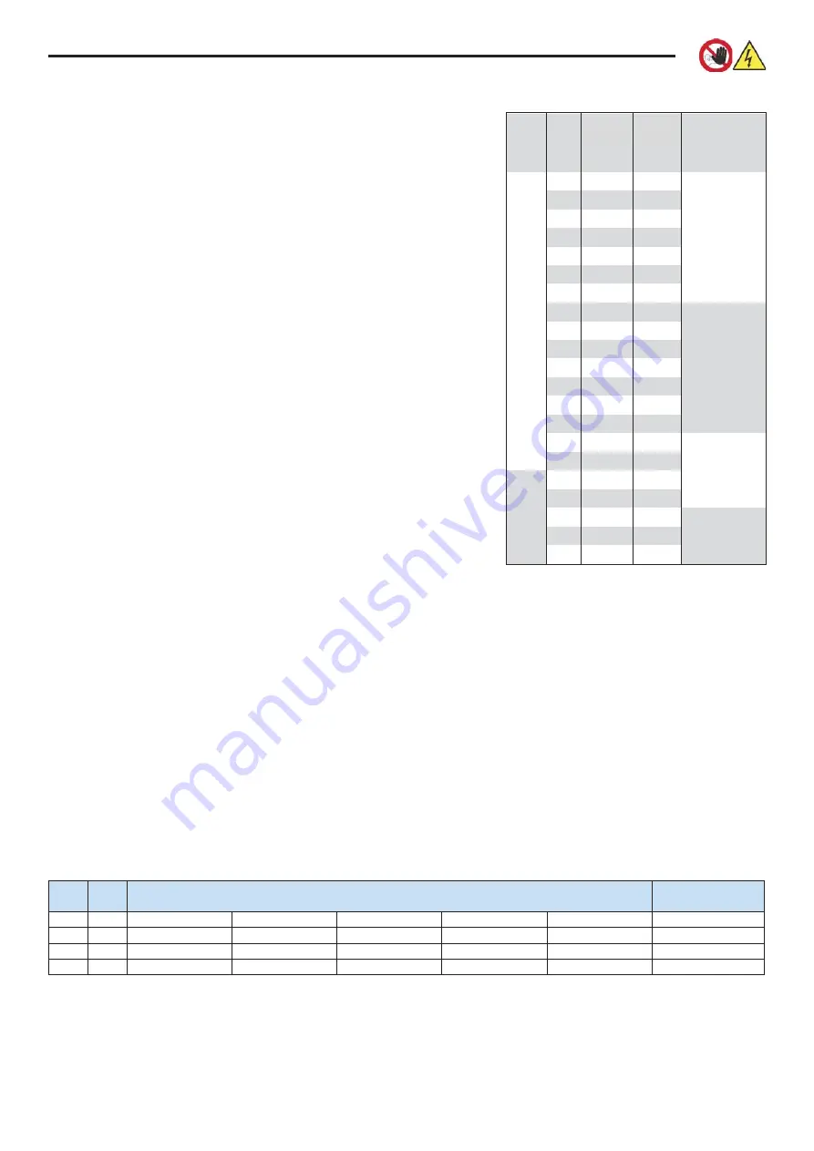
SW4-2, ENC1 - Cooling capacity setting, set the
cooling capacity of this machine (Table. 5-1).
DipSW factory settings:
SW1: 0000
(leaving the differential for thermo-off
in cooling by default at 0 ° C)
SW2: 0000
SW3: 0001
(compensation in heating 2 ° C, the
only dipSW to actually move)
SW4: 0000
SW9: 000
SW10: 00
(identifies UTA kit size)
Capacity settings:
-
KRE-500DX1
(3 kW in cooling) -> 1HP ->
SW4-2=0, ENC1=1
-
KRE-1000DX1
(5,8 kW in cooling) -> 2HP ->
SW4-2=0, ENC1=4
Содержание KRE-500DX1
Страница 1: ...KRE 500DX1 KRE 1000DX1 INSTALLATION USER MAINTENANCE MANUAL Cross flow heat recovery...
Страница 32: ......


