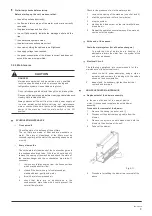
background image

I&O manual


7


cm

/m


50m

m


50m

m


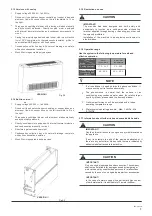
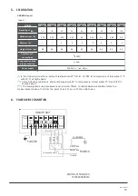
3.2.1  Hydraulic connections


Connection to the system


connect to the unit 

condensate discharge 

or defrosting tray.


IMPORTANT!


CAUTION


Fig.3-7


It is most  important  that the hydraulic connections  are made 
with great care by specialized fitters.


Connect the  unit to the water system by means of the fittings which 
are marked Flow and Return.


Creation of the trap


The  condensation  drainage  system  must  be  fitted  with  a 
suitable  trap  to  prevent  seepage  of  odors.  Following  are 
directions for setting up the trap.


Fig.3-8


Always  provide  a  drainplug  at  the  bottom  of  the  trap,  and 
arrange it so that it can be quickly dismantled


Fig.3-6


IMPORTANT!


CAUTION


All the water coils, including the optional extras, are equipped with air 
bleed-valves  next  to  the  upper  union, and  with  water  drain  valves 
need to the lower union.


All the valves can be opened and closed with screwdrivers or allen 
keys.


CAUTION


IMPORTANT!


The  water  coils  can  be  partially  drained  through  the  drain 
valves.


To  drain  them  completely, they  should  be  blown  out  with  an 
air-jet.


When installation is complete, it is necessary to:


Position the drain-tube so that it does not put strain on the 
drainage connector on the unit.


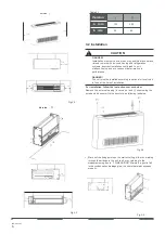
How to turn the coil round, from fittings on the left


(standard) to fittings on the right.


The  unit  is  supplied  as  standard  with  connections  to  the  coil  on  the 
left.  It  is  possible  however  to  turn  the  coil  round,  so  that  the 
connections are on the right.


The operation  of  turning  the  principal and supplementary coils round 
can  be  carried  out  with  the  unit  in  situ,  but  it  is  preferable  to  do  it 
before installation, with the unit on solid ground.


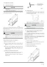
Procedure to reverse the coil:


Bleed the air contained in the circuit.


Lag  the  connection  pipes  and  any  valves  titted  with 
anticondensation  material  10  mm  thick  or  install  the  auxiliary 
drain.


Pour  water  into  the  condensation  collector  tray  and  check 
that the  liquid  drains  properly, following it  right  through to the 
exit of the drain tube. If it does not, check the fall and look for 
possible blockages.


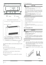
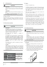
Setting up the condensate drainage system


The  condensation  drainage  system  must  be  set  up  with  an 
adequate fall, to ensure that the water escapes properly.


Following  are directions for setting up  a  proper condensation 
drainage system.


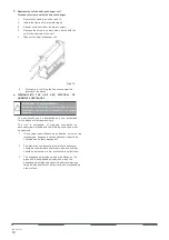
1     Remove the casing (on versions I and II);


2     Remove  the  screws  on  both  sides  which  hold  the  coil  to  the 

structure of the unit;


3     Turn the coil round in the direction indicated in Fig;


4     Re-fit the coil mounting screws;


5     Re-fit the casing (on versions I and II)


Fig.3-9


Содержание KFC-S-2T-250D

Страница 1: ...il Unit KFC S 2T 250D KFC S 2T 400D KFC S 2T 500D KFC S 2T 900D KFC SE 2T 250D KFC SE 2T 400D KFC SE 2T 500D KFC SE 2T 900D Thank you very much for purchasing our fan coil unit before using your unit please read this manual carefully and keep it for future reference ...

Страница 2: ......

Страница 3: ...t of refrigerant leakage Contact the place of purchase for more information Excessive refrigerant in a closed ambient can lead to oxygen deficiency Use the attached accessories parts and specified parts for installation otherwise it will cause the set to fall water leakage electrical shock and fire The appliance must be installed 2 3m above floor The appliance shall not be installed in the laundry...

Страница 4: ...sary Don t install the air conditioner in the following locations There is petrolatum existing There is salty air surrounding near the coast There is caustic gas the sulfide for example existing in the air near a hot spring The Volt vibrates violently in the factories In buses or cabinets In kitchen where it is full of oil gas There is strong electromagnetic wave existing There are inflammable mat...

Страница 5: ... Built in version II VERSION I Fig 2 2 2 The phenomenon is normal that the surface of air conditioning may condense water when the relative larger humidity in room please close the door and window 3 Optimum performance will be achieved within these Supply voltage 220 240V 1ph 50Hz Finned coil type heat exchanger consisting of copper tubes and aluminum fins with connections on the left reversible t...

Страница 6: ...ntroller can be only installed in 3 way valve side Information about further risks and unavoidable hazards installation manual for controller DANGER Always switch off the electric power before beginning cleaning or maintenance operations Do not spill water on the unit In versions with casing it is possible to clean the outside of the unit For cleaning use a soft cloth dampened with water and alcoh...

Страница 7: ...LATION The units should only be moved and lifted by specialized personnel trained in these operations Check on arrival that the unit has not been damaged during transport and that it is complete with all its parts DANGER Movement of the unit should be performed with care in order to avoid damage to the external structure and to the internal mechanical and electrical components Also make sure that ...

Страница 8: ... according to national or local rules in force at the time of installation For installation follow the instructions set out below Remove the external casing in versions I and II unscrewing the screws which secure it to the structure as following indicated Fig 3 2 Version a a b Fig 3 4 b a a Fig 3 3 Mark out the fixing points on the wall or ceiling either by marking through the drillings in the uni...

Страница 9: ...e drainage connector on the unit How to turn the coil round from fittings on the left standard to fittings on the right The unit is supplied as standard with connections to the coil on the left It is possible however to turn the coil round so that the connections are on the right The operation of turning the principal and supplementary coils round can be carried out with the unit in situ but it is...

Страница 10: ...qualified personnel in compliance with the regulations in effect in the country where the unit is installed The company shall not be held liable for damage to persons or property caused by incorrect electrical connection The power cord type designation is H05RN R or above H07RN F This appliance can be children aged from 8 years and above and persons with reduced physical sensory or mental capabili...

Страница 11: ...intake grilles Disconnect the power supply before cleaning and maintenance Use dry cloth to clean the unit Always disconnect the unit from the mains power supply at the main isolator switch before carrying out maintenance work or checks Make sure that no one accidentally supplies power to the machine lock the main switch in the Off position SCHEDULED MAINTENANCE Once a month Check the state of cle...

Страница 12: ...t to adhere scrupulously to the following procedures The unit should only be dismantled by a firm authorized for the disposal of scrap machinery The unit is composed of materials considered as secondary raw materials and the following conditions must be observed 1 If the system has antifreeze as an additive it must not be just dumped because it causes pollution It should be collected and suitably ...

Страница 13: ...Fig 4 1 46 105 55 140 D Fig 4 2 185 207 Fig 4 3 150 150 Fig 4 4 Table 4 1 VERSION I 150 250 300 400 450 500 600 800 900 A mm 800 800 1000 1000 1200 1200 1500 1500 1500 B mm 584 584 784 784 984 984 1284 1284 1284 C mm 500 500 700 700 900 900 1200 1200 1200 D mm 526 526 726 726 926 926 1226 1226 1226 ...

Страница 14: ...46 105 D B Fig 4 6 A C 185 Fig 4 7 Fig 4 8 Table 4 2 VERSION 150 250 300 400 450 500 600 800 900 A mm 550 550 750 750 950 950 1250 1250 1250 B mm 526 526 726 726 926 926 1226 1226 1226 C mm 500 500 700 700 900 900 1200 1200 1200 D mm 500 532 732 732 932 932 1232 1232 1232 ...

Страница 15: ...4G M 16mm Power supply 220 240V 1ph 50Hz In the following conditions ambient temperature 27 C D B 19 CW B temperature of inlet water 7 C with t5 C at high speed In the following conditions ambient temperature 20 C temperature of inlet water 70 C with t10 C at high speed The A weighted sound pressure level is below 70dB soundpressurelevelindB A refers to a measurement taken at 1m from the point of ...

Страница 16: ...MD15IU 015CW DZ1 16126200A06812 ...

Страница 17: ...I O manual 15 ...

Страница 18: ......

Страница 19: ...I O manual 17 ...

Страница 20: ......

Отзывы: