background image


Operating Manual 


Original Operating Manual


Contents 

Page


1.


Introduction

 ............................................................................................................................................. 4 


1.1


Working with this manual ......................................................................................................... 4


1.2


Warning notes and symbols ..................................................................................................... 4


1.3


Copyright .................................................................................................................................. 4


1.4


CE-Mark ................................................................................................................................... 5


1.5


Qualified and authorised personnel ......................................................................................... 5


1.6


Warranty claims based on defects ........................................................................................... 5


1.7


Limits of applicable use ............................................................................................................ 5 


2.


Safety aspects

 ......................................................................................................................................... 6 


3.


Design

 ...................................................................................................................................................... 7 


3.1


Clamping body and flange ....................................................................................................... 7


3.2


Rotator with mounting .............................................................................................................. 8


3.3


Proper use of the equipment .................................................................................................... 8


3.4


Improper use ............................................................................................................................ 9


3.5


Hydraulic oil flow required ........................................................................................................ 9 


4.


Installation and checking out

 .............................................................................................................. 10 


4.1


Installation .............................................................................................................................. 10 

4.1.1


Model T456xx without sideshiftBZ ............................................................................. 10


4.1.2


Model T496xx with sideshift ....................................................................................... 11 

4.2


Checking out .......................................................................................................................... 12 

4.2.1


Bleeding the hydraulic system ................................................................................... 12


4.2.2


Adjustment after putting into service .......................................................................... 12 


5.


Operation

 ............................................................................................................................................... 13 


5.1


General................................................................................................................................... 13


5.2


Load handling ......................................................................................................................... 13


5.3


Driving .................................................................................................................................... 14


5.4


Rotate ..................................................................................................................................... 14 


Содержание T456BZ Series

Страница 1: ...Positioner 3 5T 4 5T 456BZ 3 5T 4 5T 456BZA 3 5T 4 5T 496BZ 3 5T 4 5T T496BZA T456BZ T496BZ Rotating Fork Positioner without sideshift Rotating Fork Positioner with sideshift T456BZA T496BZA Rotating...

Страница 2: ...aspects 6 3 Design 7 3 1 Clamping body and flange 7 3 2 Rotator with mounting 8 3 3 Proper use of the equipment 8 3 4 Improper use 9 3 5 Hydraulic oil flow required 9 4 Installation and checking out...

Страница 3: ...not part of the Operating Manual 26 12 EC Declaration of Conformity Summary 26 Our service department in Aschaffenburg will be happy to answer your technical questions and to provide additional suppor...

Страница 4: ...following symbols are used in this operating manual to highlight details of special importance Identifies details relating to do s and don ts for the purpose of avoiding injury and property damage Spe...

Страница 5: ...nents Inappropriate installation maintenance inspection and servicing Assignment of unqualified or non authorised personnel Claims raised by third parties 1 7 Limits of applicable use KAUP attachments...

Страница 6: ...safe distance away from moving reciprocating or rotating parts of the attachment to avoid danger of crushing pinching or entanglement Notify the responsible department person immediately of changes a...

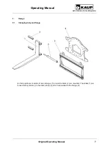
Страница 7: ...Operating Manual 7 3 Design 3 1 Clamping body and flange An fork positioner consists of two carriages 1 on which sliders 2 are mounted The slides 1 are moved with cylinders in the clamp body 3 which a...

Страница 8: ...wed on top hooks 5 and screwed on bottom hooks 6 The optional sideshift 7 is fitted with supporting rollers 8 and screwed onto the basic plate 2 3 3 Proper use of the equipment Rotating fork positione...

Страница 9: ...ment on the attachment such that the original mode of usage is changed e g fork extensions must be authorised by the manufacturer 3 5 Hydraulic oil flow required When the hydraulic oil flow is insuffi...

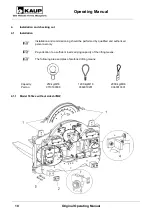
Страница 10: ...oning should be performed by qualified and authorised personnel only Pay attention to a sufficient load carrying capacity of the lifting means The following are examples of preferred lifting means Cap...

Страница 11: ...ions indicated 1 Demount the lower hooks 2 Mount the attachment on the fork carriage of the lift truck 3 Check that the attachment is correctly seated in the centre lock 4 Mount the lower hooks 2 tigh...

Страница 12: ...d before initial operation check the functions and the identification of the attached equipment with the movement directions of the operating elements operating lever joystick etc 4 2 1 Bleeding the h...

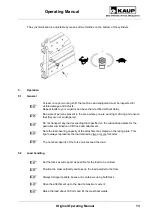
Страница 13: ...port any load exceeding that specified on the residual load plate for the particular combination of lift truck and attachment Note the load bearing capacity of the attachment as stated on the rating p...

Страница 14: ...icient distance of the load to the floor the ceiling to shelves etc If higher torque than specified is generated by the load the rotation device rotates uncontrolled or not at all This can lead to dam...

Страница 15: ...they can result in a risk of accident The EC Declaration of Conformity by the manufacturer becomes invalid and you assume full responsibility in the case of accident Use only original spare parts from...

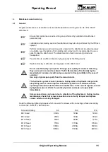
Страница 16: ...ufacturer 6 3 Schedule for routine maintenance and lubricants Lubricants approved and recommended by KAUP Greases Note Lithium soap grease NLGI Class 2 e g Avialith 2 Designation DIN51825 K 2 K 30 Com...

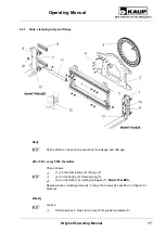
Страница 17: ...age and damage After 50h every 500h thereafter Check screws 1 on the clamp body 2 flange 3 4 on the flange 3 slewing ring 5 6 on the forks 7a sliding carriages 7 Model T4xxBZA Replace loose or damaged...

Страница 18: ...ways check the clearance between the cylinder mount and nut 12 of the cylinder 11 Cylinders are installed with axial clearance of 1 5 to 2 mm Yearly Inspect the heel of the fork 13 for wear and cracks...

Страница 19: ...Operating Manual Original Operating Manual 19 6 3 2 Rotator...

Страница 20: ...Operating Manual 20 Original Operating Manual 6 3 3 Rotator mounting without sideshift 6 3 4 Rotator mounting with sideshift...

Страница 21: ...e loose or damaged screws Torque the screws as specified in Chapter 6 1 General Weekly Grease Sliding pieces 21 by way of the greasing nipples 20 Supporting rollers 26 on the lower hooks 27 as necessa...

Страница 22: ...ieces 21 Using suitable lifting tackle lift the Fork Positioner back onto the fork carriage of the forklift truck and re assemble the hooks 25 and screws 24 Replace defective supporting rollers 26 in...

Страница 23: ...y qualified and authorised personnel Fault Possible cause Correction Clamp Opening and closing No synchronism WE throttles on the cylinder unequally adjusted Adjust the WE throttles on the cylinder Mo...

Страница 24: ...valve is too small Re bore the throttle valve or replace it with a larger one Jerky shifting action Supporting roller defective Replace supporting roller Sliders not properly lubricated Lubricate sli...

Страница 25: ...d Check weight and torque required Slides move downwards Load not clamped Clamp load Clearance Clearance too large Bevel gear defective Replace bevel gear RJ defective Replace RJ Flange tip forwards B...

Страница 26: ...llets These must not be damaged The attachment must be secured against slipping or tipping over on the support 10 Decommissioning and storage If the attachment is to be stored for an extended period a...

Отзывы: