background image

w

w

w

.

k

a

u

b

e

r

.

e

u


-3- 

MIDI is a large format series of aluminum casing, electric projection screens. Timeless design and a wide 

selection of projection surfaces makes it the most frequently selected screen for installation in assembly 

halls, lecture rooms and large conference and halls and auditoriums. 


IMPORTANT!!! 

REMARKS ON INSTALLATION AND USE


1.


The screen’s lower casing and bar are protected against damage using a polyurethane foam and tapes. 
The foam and tapes which secure the casing should be removed only at step no. 4, while the foam which 
secures the lower bar only at step no. 6 of these instructions. 

2.


The screen should be mounted in a place away from moisture and intense sunlight. 

3.


To clean the product, use a soft, damp cloth. Do not use active detergents. Do not allow for water and 
other fluids to get inside the device. After cleaning, the screen should be carefully wiped, removing any 
remaining moisture. 

4.


A correctly mounted screen must be absolutely level in every plane.


5.


No more than one control switch can be connected to the screen/lift at one time. 

6.


One control switch (e.g. RC01/RC02/Trigger 12V/Trigger 230V/IR Receiver/RS Receiver, etc.) cannot 
be connected to more than one device, like a screen, lift, roller-blind, etc., at a time.


Package contents: 

Quantity


Projection screen  

1 pcs. 

Mounting holder 

3 pcs. 

Mounting angle bracket 

3 pcs. 

Ø14 anchor plug for wall mounting 


12 pcs. 

M6x12 screw 

12 pcs. 

M6 washer 

12 pcs. 

L-shaped screen locking and securing bar 

6 pcs. 

Screen hanging chain 

2 pcs. 

Key for screen end position adjustment 

1 pcs. 

Wall-mounted pushbutton switch (available with screens without built in radio 
control) 

1 pcs. 


Switch 

Switch 

Controller 

Screen/lift 

motor 

Screen/lift 

motor 

Screen/lift 

motor 

Содержание MIDI

Страница 1: ...w w w k a u b e r e u 1 PROJECTION SCREEN ASSEMBLY INSTRUCTIONS MIDI ...

Страница 2: ...w w w k a u b e r e u 2 ...

Страница 3: ...etergents Do not allow for water and other fluids to get inside the device After cleaning the screen should be carefully wiped removing any remaining moisture 4 A correctly mounted screen must be absolutely level in every plane 5 No more than one control switch can be connected to the screen lift at one time 6 One control switch e g RC01 RC02 Trigger 12V Trigger 230V IR Receiver RS Receiver etc ca...

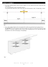
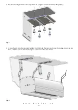
Страница 4: ...ng at the end of the instruction in the Technical data section Fig 1 2 Screw the mounting holders to the wall using the Ø14 anchor plugs included in the package Fig 2 ATTENTION The anchor plugs provided in the package can only be used with walls made out of solid materials e g concrete aerated concrete In the event of mounting the screen to materials other than stated above select other anchor plu...

Страница 5: ... to the angle brackets using the screws included in the package Fig 3 4 Attach the screen to the mounted holders In order to do this more easily use the chains which you can hold to lift the screen After mounting the screen disconnect the chains Fig 4 ...

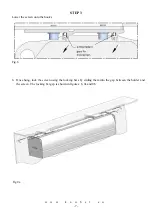
Страница 6: ...hment system is visually presented in the figures below To attach the screen perform the following 3 steps Fig 5 STEP 1 Raise the screen upwards so that it touches the mounting holders Fig 6 STEP 2 Move the screen towards the hooks Fig 7 ...

Страница 7: ...u 7 STEP 3 Lower the screen onto the hooks Fig 8 6 Once hung lock the screen using the locking bars by sliding them into the gap between the holder and the screen The locking bar gap is shown in figures 8 9a and 9b Fig 9a ...

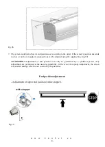
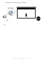
Страница 8: ...s can be adjusted using the supplied key fig 10 ATTENTION Adjustment of end positions can only be performed by a qualified person Any adjustments are performed at the users responsibility In the event of improper adjustment the screen may sustain damage which is not covered by the guarantee End position adjustment Adjustment of upper end position white stopper Fig 10 white stopper ...

Страница 9: ...w w w k a u b e r e u 9 Adjustment of lower end position yellow stopper Fig 11 yellow stopper ...

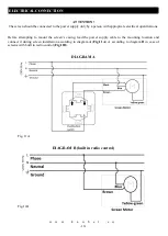
Страница 10: ...te electrical qualifications Before attempting to mount the screen s casing lead the power supply cable to the mounting location and connect it during screen installation according to diagram A Fig 11A or according to diagram B in case of screens with built in radio control Fig 11B DIAGRAM A Fig 11A DIAGRAM B built in radio control Fig 11B ...

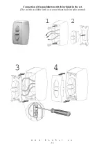
Страница 11: ...w w w k a u b e r e u 11 Connection of the pushbutton switch included in the set The switch available with a screen without built in radio control ...

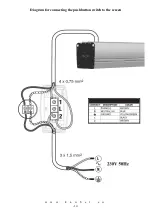
Страница 12: ...w w w k a u b e r e u 12 Diagram for connecting the pushbutton switch to the screen ...

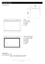
Страница 13: ...face height F A 96mm J A 40mm K 50mm MIDI BLACK FRAME A active surface width B active surface height C A 100mm D B 100mm F A 196mm J A 140mm K 50mm Technical data Power supply 230V 50Hz Power consumption 160W screen without built in radio control 240W screen with built in radio control ...

Страница 14: ...w w w k a u b e r e u 14 ...

Страница 15: ...w w w k a u b e r e u 15 ...

Страница 16: ...w w w k a u b e r e u 16 Thank you for choosing the KAUBER screen You are welcome to purchase other KAUBER brand products ...

Отзывы: