Kauai Labs navX2-MXP Скачать руководство пользователя страница 63

Guidance

Best Practices

isCalibrating() function) before using navX-sensor data.

4) If using the MXP connector, secure the navX-sensor circuit board
to the RoboRio

During operation of the robot, certain actions (for instance, driving over a bump at high speed) may cause
the navX-sensor circuit board to become dislodged from the MXP connector.

To avoid this case, when 

mounting

 the navx-sensor circuit board to the RoboRIO MXP port, be sure to

secure the navX-sensor circuit board firmly to the RoboRio via two correctly-sized screws.

5) Protect the Sensor

navX-sensors contain sensitive circuitry. The navX-sensor circuit board should be handled carefully.

An 

enclosure

 is recommended to protect the navX-sensor circuit board from excessive handling, “swarf”,

electro-static discharge (ESD) and other elements that could potentially damage navX-sensor circuitry.
The enclosure can also help prevent accidental shorts to ground which may occur on the MXP Expansion
I/O pins.

6) Plan for Catastrophic Sensor Failure

Any electronic component can fail or become disconnected accidentally. To ensure that your robot can
still function during a FRC match even if such a failure does occur, your robot software should handle
cases when communication with sensors such as the navX-sensor is disrupted.

An easy way to accomplish this is to use the “isConnected()” indication, and only use navX-sensor data
to control your robot when this is true.

Additionally, displaying whether the robot software is connected to the navX-sensor circuit board on the
driver “dashboard” can help the drivers quickly detect a connection problem.

7) Provide a “Zero Yaw” feature (for Field-Oriented Drive)

The navX-sensor gyro “yaw” angle will 

drift

 over time; the amount of drift depends upon the generation

of navX-sensor (“Generation 2” navX2-sensors drift less than “Classic” navX-Sensors) and also how
firmly the navX-Sensor is mounted to the chassis. While this does not normally impact the robot during a
FRC match, if using field-oriented drive during extended practice sessions it may be necessary to
periodically “zero” the yaw. Drivers should be provided a simple way (e.g., a joystick button) with which
to zero the yaw.

8) Avoid shorts on Expansion I/O pins

 60

Содержание navX2-MXP

Страница 1: ...navX2 MXP Robotics Navigation Sensor User Guide Kauai Labs Creative Commons BY 2020...

Страница 2: ...RIO Libraries 30 Android Library FTC 31 Linux Library 33 Arduino Library 33 navXUI 34 Tools 37 Examples 38 Examples 38 Field Oriented Drive FRC 38 Rotate to Angle FRC 42 Automatic Balancing FRC 45 Col...

Страница 3: ...Serial Protocol 81 Register Protocol 86 Open source Hardware Software 90 Classic navX MXP Firmware Customization 90 navXUI Customization 95 Technical References 96...

Страница 4: ...xpansion Generation 2 navX2 MXP is a drop in replacement for Classic navX2 MXP See the Frequently Asked Questions FAQ for more information about navX2 MXP improvements navX2 MXP is a must have add on...

Страница 5: ...eading 9 Axis absolute heading w Magnetic disturbance detection Configurable Update Rate from 4 to 200Hz Easy to Use Plug n Play Installation via RoboRIO MXP Interface USB TTL UART I2C and SPI communi...

Страница 6: ...Current Consumption 60 millamps Communications Interfaces USB TTL UART SPI I2C Power Connector USB and or 5VDC GND Pins on MXP Connector Power Source Fail over Automatic switch between USB MXP Power w...

Страница 7: ...ng and Control has six chapters that focus on CAD modeling traditional machining CNC mills and lathes CNC cutting 3D printing and sensors control Each chapter profiles five FRC teams to illustrate how...

Страница 8: ...16G accelerometer data As a result of these enhancements Startup time is reduced to only 5 seconds Pitch Roll accuracy is increased to 0 5 degrees Errors due to Extreme inertial events are minimized T...

Страница 9: ...he RoboRIO Please see the instructions for installing navX2 MXP onto a FIRST FRC robot for more details as there are several installation options Will navX2 MXP work with the Android based FTC Control...

Страница 10: ...w Drift page Can the navX2 MXP Displacement estimates be used for tracking a FRC or FTC robot s change in position dead reckoning during autonomous Accelerometer data from the navX MXP s onboard MPU 9...

Страница 11: ...available at low cost will likely occur in the next decade but technology has not advanced to this point yet KauaiLabs plans to develop a product which can be used for accurate accelerometer based dea...

Страница 12: ...2 MXP also provides analog and digital I O expansion on a RoboRIO Flexibility To allow flexible customization navX2 MXP also supports several alternative installation options as well as several commun...

Страница 13: ...Installation RoboRIO Installation 10...

Страница 14: ...oard in an area of the chassis that might be flexible as this could introduce vibration to the inertial sensors that does not represent the chassis inertial properties The navX2 MXP circuit board shou...

Страница 15: ...pins to the corresponding pins on the navX2 MXP External I2C Port Connector NOTE The I2C to JST PH Cable linked to above has a different pin out on the 1 Molex black plastic header side than found on...

Страница 16: ...X2 MXP Physical Installation on the Robot The navX2 MXP circuit board should be mounted such that it is firmly attached to the robot chassis The quality of this mounting will be directly reflected in...

Страница 17: ...ordinate system In order to effectively use the values reported by navX2 MXP a few key concepts must be understood in order to correctly install navX2 MXP on a robot 3 D Coordinate System When control...

Страница 18: ...Front Head of Field Robot Body Frame Side of Robot Front Head of Robot navX2 MXP Board Frame See diagram Below See diagram below Joysticks and Reference Frames Since a three axis joystick is typicall...

Страница 19: ...directly up and down with respect to the earth When installing navX2 MXP on a robot the navX MXP yaw Z axis and the gravity axis must be aligned Default navX2 MXP Board Orientation The default navX2 M...

Страница 20: ...Installation Orientation 17...

Страница 21: ...e down In certain cases the navX2 MXP axes Board Frame may not be oriented exactly as that of the Robot Body Frame For instance if the navX2 MXP circuit board is plugged directly into the RoboRIO MXP...

Страница 22: ...similar to how a modern smart phone will rotate the display based upon the phone s orientation However unlike a smart phone the OmniMount detection of orientation does not happen all the time since th...

Страница 23: ...libration During this auto calibration period the orange CAL LED will flash repeatedly This process takes approximately 15 seconds and requires two things 1 During auto calibration one of the navX2 MX...

Страница 24: ...Installation I O Expansion 21...

Страница 25: ...and Signal The orientation of the Ground Power and Signal pins for each of the Digital I O Analog Input and Analog Output pins is as follows Digital I Os Each of the 10 Digital I O pins may be config...

Страница 26: ...se Analog Inputs Each of the 4 Analog Input pins on the MXP connector has a corresponding 3 pin connector DC Voltage Ground and Signal On the RoboRIO these signals are routed to the internal Analog to...

Страница 27: ...p switch is set to the ON position Thus the SPI Enable dip switch should be set to the OFF position if you wish to communicate with an external device via the SPI connector TTL UART The navX2 MXP TTL...

Страница 28: ...ference so high quality shielded cabling and shorter distances may be called for These extension cables are available online at AndyMark Image not found One wire Connect via USB cable By using a USB M...

Страница 29: ...a pull up resistor on each line The RoboRIO internally pulls these lines high The I2C pins are 5V tolerant so the host computer can use either 5V or 3 3V DC levels on these pins SPI To use the SPI int...

Страница 30: ...TL format is available in the enclosure directory of the Those who prefer to purchase the enclosure can order it from Shapeways which takes approximately 2 weeks to deliver or at the Kauai Labs store...

Страница 31: ...extension Finally these exported STL format files can be opened and 3d printed using netfabb Securing the Enclosure The Lid Enclosure can be secured to the RoboRIO by two 4 40 1 2 screws This will sec...

Страница 32: ...so available Note For developers on Linux and Mac OS platforms the latest non Windows RoboRIO FRC Android FTC libraries build is also available Please note that this build does not contain any of the...

Страница 33: ...g Started Before getting started ensure you have installed Android Studio and the indicated Android Studio Project components linked to on the FIRST Tech Challenge Programming Resources page Several s...

Страница 34: ...es flatDir dirs libs C Users Robot navx mxp android libs Again in the same build release gradle file add the navx_ftc library to the list of libraries the ftc_app will link to by adding this line near...

Страница 35: ...e navX sensor Linux Library is useful for integrating with video processors such as the Raspberry PI and the Jetson TK1 and TX1 To use the library you can checkout the source code with Git Online help...

Страница 36: ...To use the library you can checkout the source code with Git Getting Started After checking out the source code with Git into a directory on your computer compile using the Arduino IDE The file navXT...

Страница 37: ...see the Gyro Accelerometer Calibration page Motion Indicators The navX sensor provides dynamic motion indicators a the Moving indicator and b the Rotating indicator The Moving indicator is present wh...

Страница 38: ...turbance is indicated Yaw Angle The Yaw Angle is displayed in grey text if Gyro Calibration has not yet been completed Once Gyro Calibration is complete the Yaw Angle text color will change to white P...

Страница 39: ...e program which will install the navXUI as well as all necessary device drivers for communicating over USB with the navX sensor as well as some additional tools Start the navXUI From your Start Menu s...

Страница 40: ...he setup program contained in the latest build Java C examples will be installed to subdirectories underneath navx mxp examples vscode e g C Users Robot navx mxp cpp examples vscode These examples are...

Страница 41: ...lar transformation mentally This skill can take quite awhile to develop meaning that rookie drivers face an uphill climb before they can be productive team contributors Additionally the mental energy...

Страница 42: ...lent post on Chief Delphi by Ether which provides a wealth of helpful well written information on implementing field centric drive on various types of drive systems FRC C Example Full C source code on...

Страница 43: ...eading to the Holonomic Drive VI which rotates the joystick X Y coordinates by the gyro angle and thus implements FieldCentric drive control Additionally if a driver joystick button is pressed the nav...

Страница 44: ...te to preset angle button is pressed This rotation can occur not only when the robot is still but also when the robot is driving When using field oriented control this will cause the robot to drive in...

Страница 45: ...abView Example The navX sensor Rotate to Angle LabView example shows how to make small modifications to the LabView FRC RoboRIO Robot Project using the Mecanum Robot configuration to rotate the robot...

Страница 46: ...dinates by the gyro angle and thus implements FieldCentric drive control Additionally if a driver joystick button is pressed the navX sensor Yaw angle is reset to zero This example also includes a Rot...

Страница 47: ...he X axis and Roll rotation about the Y axis angles When these angles exceed the off balance threshold and until these angles fall below the on balance threshold the drive system is automatically driv...

Страница 48: ...how to make small modifications to the LabView FRC RoboRIO Robot Project using the Mecanum Robot configuration to implement high accuracy Automatic Balancing RobotMain vi Place the NavX main vi on th...

Страница 49: ...FieldCentric drive control Additionally if a driver joystick button is pressed the navX sensor Yaw angle is reset to zero Finally the navX sensor Pitch X axis and Roll Y axis angles are continuously...

Страница 50: ...es during an accident A similar technique can be used on a robot to detect when it has collided with another object The principle used within the Collision Detection example is the calculation of Jerk...

Страница 51: ...l be dependent upon the robot mass and expected maximum velocity of either the robot or any object which may strike the robot FRC C Example Full C Source Code FRC Java Example Full Java Source Code FR...

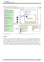
Страница 52: ...y need to process faster for your situation For the SPI I2C and USB connections the max sample rate is 200Hz Teleop vi The Teleop vi is modified to feed the Linear Acceleration to a threshold detector...

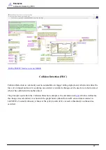
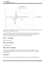
Страница 53: ...ecting motion with raw acceleration data is to use a high pass filter which lets quickly changing information through but blocks information that doesn t change frequently However a more comprehensive...

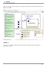
Страница 54: ...small modifications to the LabView FRC RoboRIO Robot Project using the Mecanum Robot configuration to detect when your robot is moving RobotMain vi Place the NavX main vi on the block diagram and set...

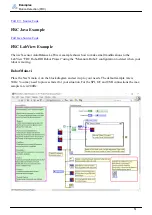
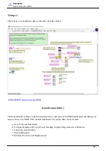
Страница 55: ...Data Monitor example code demonstrates how to perform navX MXP initialization and display all sensor values on a FIRST FRC robotics dashboard The output data values include Yaw Pitch and Roll angles...

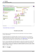
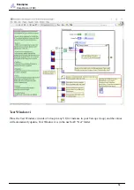
Страница 56: ...C source code on GitHub FRC Java Example Full Java Source code on GitHub FRC LabVIEW Example The navX sensor Test_Window vi example shows all of the outputs from the navX sensor through FRC RoboRIO R...

Страница 57: ...Data Monitor FRC Test Window vi Place the Test Window vi inside of a loop in any VI for instance in your Teleop vi loop and the values will automatically update Test Window vi is in the navX AE Get f...

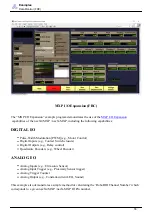
Страница 58: ...g Motor Control Digital Inputs e g Contact Switch closure Digital Outputs e g Relay control Quadrature Encoders e g Wheel Encoder ANALOG I O Analog Inputs e g Ultrasonic Sensor Analog Input Trigger e...

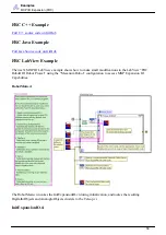
Страница 59: ...View example shows how to make small modifications to the LabView FRC RoboRIO Robot Project using the Mecanum Robot configuration to access MXP Expansion IO Capabilities RobotMain vi The RobotMain vi...

Страница 60: ...onto the navX MXP Expansion IO Pins GetChannelFromNavX MXPPin vi The GetChannelFromNavX MXPPin vi performs the translation from the navX2 MXP navX MXP Digital or Analog Pin number to the correspondin...

Страница 61: ...ck inputs and programs the output pins accordingly PWM to motor controllers Digital Outputs and Analog Outputs As well values from the input pins Digital Inputs Encoders and Analog Inputs is retrieved...

Страница 62: ...or restarts is very important if your robot software uses the yaw angle To avoid a navX sensor restart when stage 2 brownouts occur a secondary power supply for the navX sensor circuit board should be...

Страница 63: ...y electronic component can fail or become disconnected accidentally To ensure that your robot can still function during a FRC match even if such a failure does occur your robot software should handle...

Страница 64: ...ot mounted horizontally By default the navX sensor s motion processing requires the unit be mounted horizontally parallel to the earth s surface the yaw Z axis should be perpendicular to the earths su...

Страница 65: ...navX sensor Pitch and Roll angles are referenced to earth s gravity so when a navX sensor is flat Pitch and Roll angles should be very close to 0 The Yaw angle is different Yaw is not referenced to a...

Страница 66: ...orth and thus Compass Heading does not drift over time Important Note 1 Compass Heading relies upon being able to measure the earth s magnetic field Since the earth s magnetic field is weak Compass He...

Страница 67: ...used to uniquely determine the position of a point within a space measured by that system The origin of a 3 D coordinate system has a value of 0 0 0 navX sensors feature gyroscopes accelerometers and...

Страница 68: ...otation similarly Fused Heading Given the gravity referenced orientation provided by the Yaw angle as well as the absolute compass heading angle which has been aligned to the navX sensor 3 D coordinat...

Страница 69: ...lacement estimation can be several feet per second As MEMS sensors improve in the coming years and accelerometer noise is reduced this technique will become more useful for robotics navigation If you...

Страница 70: ...ns internally and also provide the 4 quaternion values for use by those who might need them Selecting an Interface The navX2 MXP navX MXP sensors provide several methods for communicating with robotic...

Страница 71: ...away from motors This configuration is also useful when accessing navX sensor data from a separate processor such as a PC or a separate video processor However please note that in certain cases when...

Страница 72: ...Guidance Gyro Accelerometer Calibration The navX sensor Calibration Process is comprised of three calibration phases Factory Calibration Startup Calibration On the fly Calibration 69...

Страница 73: ...ation Factory Calibration Before navX sensors are shipped the accelerometers and gyroscopes are initially calibrated at the factory this calibration data is stored in flash memory and applied automati...

Страница 74: ...that yaw accuracy will be diminished until the next On the fly Gyro Calibration completes Second Generation navX sensor Factory Calibration Time if still 2 seconds Classic navX sensor Factory Calibrat...

Страница 75: ...on So once again it s important to keep the sensor still during Startup Calibration Runtime Yaw Zeroing Your robot software can optionally provide the robot operator a way to reset the yaw angle to Ze...

Страница 76: ...etometer Calibration tool This tool is designed to run on a Windows computer and communicate to the navX sensor circuit board via a USB cable Yaw Drift A gyroscope measures the amount of angular rotat...

Страница 77: ...e the accelerometer values in this axis are the same no matter how much yaw rotation exists To deal with this several different data fusion algorithms have been developed including Complementary filte...

Страница 78: ...long practice matches the drift may become noticeable and can be dealt with using the following approaches 1 The simplest approach which is supported by the navX sensor libraries is to periodically r...

Страница 79: ...motors are energized If the sensor is placed far enough away from motors it may be possible to also get an undisturbed magnetometer during a match Finally note that the resulting angle is only as accu...

Страница 80: ...Please visit navX Sensor Support to access the firmware archive Factory Test Procedure The Factory Test Procedure verifies correct operation of the circuit board and it s key components Please visit...

Страница 81: ...va Added VSCode specific software examples 2019 FRC Season Release Version Number 3 1 339 Change Summary Firmware Changed default serial protocol to the most commonly used protocol reducing startup ti...

Страница 82: ...g 2016 FRC Season Release Version Number 3 0 263 The cross platform build is also available for non Windows platforms Change Summary Firmware Added new Omnimount capabilities Firmware Added new onboar...

Страница 83: ...adding support for the navX sensor protocol to a software project Message Structure ASCII Protocol Messages Each navX sensor Serial ASCII protocol message has the following structure Start of Message...

Страница 84: ...ed Hundredths original value 100 rounded to nearest integer Signed Hundredths original value 100 rounded to nearest integer Signed Thousandths original value 1000 rounded to nearest integer Signed Pi...

Страница 85: ...feed character Checksum The checksum is calculated by adding each byte of the message except the bytes within the Message Termination itself The checksum is accumulated within an 8 bit unsigned byte N...

Страница 86: ...Integer 4 Gyro Y 15 bits signed 16 bit Integer 8 Gyro Z 15 bits signed 16 bit Integer 12 Acceleration X 16 bits signed 16 bit Integer 16 Acceleration Y 16 bits signed 16 bit Integer 20 Acceleration Z...

Страница 87: ...he Stream Configuration Command is sent in order to change the type of navX sensor Streaming Update transmitted to the client Byte Offset Element Data Type 0 Stream Type 8 bit ASCII Character 1 Update...

Страница 88: ...r based protocol This page documents the register based protocol used on both the I2C and SPI bus Register based protocol overview Unlike the streaming Serial protocol which periodically sends out upd...

Страница 89: ...ead from the navX sensor The I2C bus master next sends the starting register address it intends to write to or read from The I2C bus master next initiates I2C bus transactions The navX sensor supports...

Страница 90: ...registers it wishes to read from This count must be at least 1 and must be not exceed the maximum register address less the requested register address If the SPI bus master is writing it transmits the...

Страница 91: ...code to calculate the CRC value please see Line 445 of the IMURegisters h source code navX sensor Register Data Types All multi byte registers are in little endian format All registers with signed da...

Страница 92: ...e Hardware Software Classic navX MXP The navX MXP project is completely open source including schematics firmware and design files for an enclosure These sources are available online at the navX MXP G...

Страница 93: ...or 64 bit Windows it is installed into C Program Files x86 CodeSourcery Sourcery G Lite Add the path to the bin director underneath the Code Sourcery G Lite installation directory so that the compiler...

Страница 94: ...e unfamiliar with installingn Eclipse plugins please visit this URL for more information on the process https wiki eclipse org FAQ_How_do_I_install_new_plug ins 3F Zylin Plugin Update URL http opensou...

Страница 95: ...digikey com among others for approximately 40 Additional utilities for the ST LINK V2 for windows are available on the STM website Connecting the ST LINK V2 to the navX MXP Circuit Board You will nee...

Страница 96: ...nformation on how to proceed Configure Eclipse to run OpenOCD Run External Tools External Tools Configuration Add a new configuration name it OpenOCD In the main tab under Location provide the path to...

Страница 97: ...0 script file to reference your particular directory path to the navx mxp distribution directory you unpacked the navx mxp distribution zip into Once the debug configuration is created and the open oc...

Страница 98: ...play Technical References The references on this page are provided to help students gain a deeper understanding of the algorithms technologies and tools used within the navX sensor and other Inertial...

Отзывы: