Measurement Screen
The main measurement unit is dis-
played when first entering the mea-
surement screen. Press
MUX to switch
between channels 1 and 2. Press
NEXT to cycle through the three line
display, totaliser and dual measure-
ment screens.
Totaliser
The totaliser is shown when in meas-
urement mode after pressing
NEXT
twice. It can also be assigned to the
three line display, datalogger or pro-
cess outputs by selecting a quantity
as the unit.
Internal Datalogger
• The datalogger is reached via
Main Menu - Output. It is activated
in
Datalogger - Interval by entering and confirming a non-zero
value and selecting units to be recorded. Up to ten measurement
units can be selected for logging under
Datalogger - Selection.
• Enter an interval of "0" and confirm to disable the logger.
• Use the cursor keys to highlight a unit and press
ENTER to select
it. Press "0" to deselect it.
• An activated datalogger is indicated by a “document” symbol in
the top left corner of the display. On start of measurement (mea-
surement screen displayed) the logger records the selected mea-
surement units.
• A blinking “document” symbol indicates a recording datalogger.
Separation markers are set by the datalogger whenever a session
begins.
• Leave the measurement screen by pressing
ESC to stop recording.
• The recording interval can be changed in
Datalogger - Interval.
• The datalogger is cleared using
Datalogger - Log Erase. Ensure
all required data has been downloaded.
• The totaliser function is started with
Q
ON
when in measurement
mode (measurement screen displayed). Pressing
Q
+
resets the
total in positive flow direction. Pressing
Q
-
resets the total in neg-
ative flow direction. The totaliser function can be stopped
with
Q
OFF
.
• Pressing
Q
ON
again will reset the positive, negative and overall
totaliser. Change displays without resetting the totaliser by
pressing
DISP or NEXT.
1: 1 pass (diagonal mode)
2: 2 passes (reflection mode)
3: 3 passes (diagonal mode)
4: 4 passes (reflection mode) etc.
Select
Start Measurement and con-
firm with
ENTER to start the sensor
positioning procedure. When both
channels have been activated, the
procedure for
CH2 follows the one of
CH1.
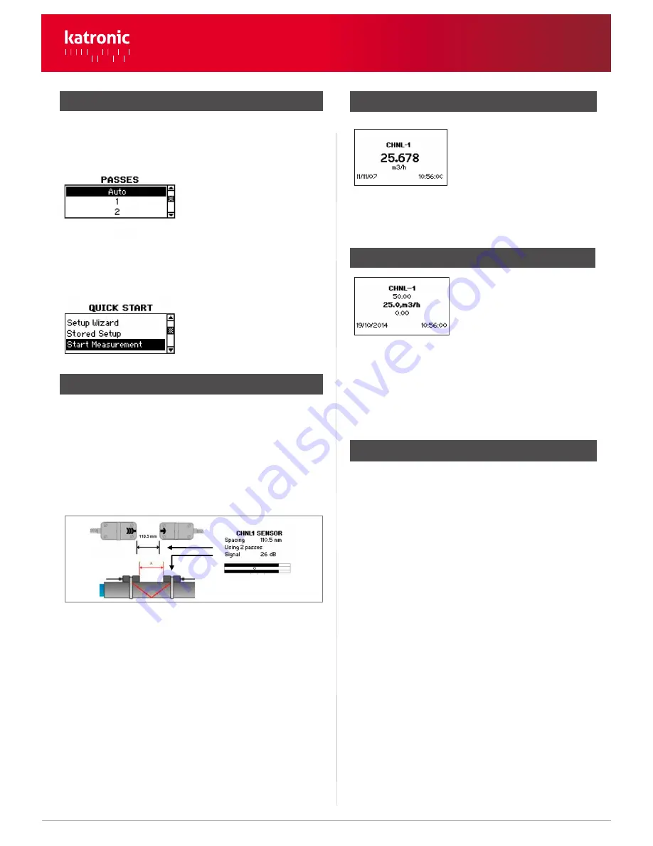
Sensor Positioning Screen
• Mount the transducers with the suggested spacing between the
sensor heads. This distance has been determined by the flow-
meter on the basis of the entered parameters.
• Use the displayed number of passes to install the sensors on the cor-
rect side of the pipe (see pictures 3 and 4).
• Observe the upper bar (signal-to-noise ratio) and lower bar (signal
quality). These should be both filled to about the same level with a
filling level of around 1/3 or more desired.
• Even number of passes: Both sensors on same side ofpipe (see pic. 3).
• Odd number of passes: Sensors on opposite sides (see pic. 4). Con-
firm with
ENTER. The second channel can now be prepared by
selecting
Setup Wizard CH2.
Step 3: Quick Start Menu and Setup Wizard (continued)
• Use the cursor between the two signal bars for fine adjustment
of the sensor position. With correct pipe parameters entered and
the sensors mounted at the suggested spacing, the mark should be
near the central indication line (see three lines below the bottom
signal bar).
• If the mark is to the left-hand side of the central indication line, the
sensors are too close to each other. If the mark is to the right, the sen-
sors are too far apart. Slide one sensor carefully along the pipe to
bring the mark into a more central position. Measurements can be
obtained when the mark is between the left and right indication
line. Press
ENTER to start measurement.
5. Sensor positioning screen
2/3
• Select number of sound passes (sound paths) using cursor keys.
•
Auto: Selection by flowmeter according to entered parameters (num-
ber of passes shown later on
Sensor Positioning Screen
).
• Two further measurement units can be assigned to the three line
screen by going to
Main Menu - Output - Display - Channel 1/
Channel 2.
www.katronic.co.uk
KATflow 150 Quick Start Manual
KATflow 150
Quick Start Manual


