background image


Use a screwdriver to detach the rounded plate covering the hole in the inner back mantle. Move 
this  covering  plate  onto  the  hindmost  hole  on  top  of  the  stove.  Place  the  connection  pipe 
delivered with the stove in its rear wall opening. Push the stove into its place. Make sure that the 
connection pipe settles well into the hole in the chimney. Tighten the space between connection 
pipe  and  chimney  with  a  flexible,  fire-proof  material  such  as  fire  wool.  Neaten  the  hole  with  a 
Kastor covering, available at your hardware store. The covering is attached to the brick chimney 
surface with metal attachments or fireproof glue. (Picture 2.4.) 


2.5.2.

 Heaters installed through the wall, KARHU-JK general


Stoves with extended feed doors must only be installed into walls made of non-

flammable material (brick, concrete etc.).

The non-flammable material must be 

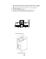
arranged around the door extension as shown in picture 6. If there is a flammable floor in 
the room with the door, the area requiring protection must extend 100mm beyond both 
sides of the door and at least 400mm in front of it. The protective layer should be a metal 
sheet with a thickness of at least 1mm.(


protective plate on the floor).


The floors of the sauna and the room into which the stove door opens must be on an equal 

level. The room with the stove door may also be on a lower level, but never higher than 
the sauna's floor! 

The stove and its extension must be installed on a sturdy, immovable, fireproof, level 

surface. A cast concrete base is the best choice. If the floor of the room with the 

door  in  it  is  flammable,

  there  must  be  a  non-flammable  protective  layer  (i.e.  cast 

concrete  or  masonry)  of  at  least  60mm  beneath  the  door  extension.  The  fire  protection 
measures on the door side must also adhere to the instructions in chapter 2.3. 

By  adding  fireproofing  the  stove  and  its  door  extension  may  also  be  installed  on 

wooden floors.

  Nevertheless,  the  dividing  wall  must  be  non-flammable (brick,  concrete 

or  similar).  For  the  sauna  and  the  extended  door,  a  concrete  slab  with  a  thickness  of 
60mm  is  usually  acceptable  (remember  to  take  care  of  moisture  draining).  The 
fireproofing on the sauna side floor must extend 100mm in front of the stove, 50mm at its 
sides  and  50mm  behind  it  or,  at  the  back  and  sides,  up  to  a  fireproofed  wall.  The  fire 
protection measures on the door side must also adhere to the instructions in chapter 2.3. 


In unclear cases consult the local fire safety officials. 


2.5.3.  INSTALLATION THROUGH THE WALL AND FITTING THE FRAME , KARHU-12–

20-27-37 JK models, also with water tank 

See also the instructions in chapter 2.6. concerning flue pipe installation. 
Make sure that you have received the frame that belongs to the door extension (behind the 

stove, between the packing hoop and the stove). 

Installation through the wall: 

  Make a hole in the wall. Its size should leave about 10-20mm of clear space all around 

the door extension. 

  Remove the stove door by taking the hinge pin off (note the 2 base plates between door 

and frame). 

  Remove the ash door. 

  Install the stove from the sauna side and push it as far as possible through the wall, so 

that the door extends about 40mm beyond the wall. 

  Insulate  the  gap  between  feed  door  and  wall  with  fireproof  mineral  wool.  Follow  the 

instructions of the mineral wool manufacturer! 

  Install the frame into place via the door (do not yet attach it to the wall). 

  Attach  the  door.  Remember  the  base  plates.  At  this  point,  you  may  choose  the  door's 

opening direction. 

  Place the rivet in the upper part of the frame in the remaining hole. 

  Put the ash door into place. 

9


Содержание Karhu PK Series

Страница 1: ...KASTOR KARHU PK PK series wood burning sauna stoves installation and usage manual Karhu PK 007 12 16 20 27 37 18 ES 20V 27V 27ES 37V and JK models 1...

Страница 2: ...ly in KARHU models 2 5 2 KARHU JK heaters with an extended fire door 2 5 3 Installing through the wall and fitting the front frame JK models 16 20 27 37 2 5 4 Connecting from the top KARHU and KARHU J...

Страница 3: ...le material procured from reliable suppliers we have gathered over the years The steel is Finnish structural steel from Ruukki which can be bent into various solutions while retaining its hardness due...

Страница 4: ...nsported in an upright position All sticker labels and packaging material must be removed before the heater is used Type plate and the CE marking must not be removed The ash pan must be closed during...

Страница 5: ...her flammable material on the heater is forbidden due to fire risk In order to guarantee full power and safety the fire door must always be kept shut when heating The fire door can be open when heatin...

Страница 6: ...e no more fumes rising from the stove Once the stove has cooled down after the burn in move it into the sauna See to it that the sauna is well ventilated during the first couple of heating 2 1 2 SIDE...

Страница 7: ...ot give a general rule of thumb you will find the right mix by trial and error For the stove s proper functioning it is essential that the hot air circulates between the stones to heat them quickly If...

Страница 8: ...2 Reduction of safety distances Kastor protective walls and a stand are available picture 7 2 3 The chimney s isolated part must reach the protective wall Other protection is not needed If the sauna...

Страница 9: ...oor extension The fire protection measures on the door side must also adhere to the instructions in chapter 2 3 By adding fireproofing the stove and its door extension may also be installed on wooden...

Страница 10: ...a factory built Kastor chimney check 2 4 Make sure to choose the correct chimney type with regard to your stove model chimney height temperature class T 600 exterior circumstances etc For best results...

Страница 11: ...chimney might suffer damage Do not throw water directly at the glass door The stove s operating life shortens if it is constantly heated to a red glow The stove s working life will be shortened signif...

Страница 12: ...tove constantly to a red glow 3 4 Lighting Place small logs into stove parallel to the grate Amounts and total per table 2 Add kindlings under the logs and light them You can keep the fire door open f...

Страница 13: ...a fails to work as you think they should go through the following check list First to make sure you have chosen the correct stove for your sauna s requirements look through the stove choosing instruct...

Страница 14: ...connecting pipe which is red hot although the lower end of the stove within the mantle is not red See chapter 3 2 about draught adjustment and heat output Is the draught too weak See chapter 3 2 about...

Страница 15: ...is a smell of sulphur in the sauna Traces of sulphur have remained on the stones from the quarry s explosion or the stones are naturally sulphurous 6 Manufacturer s declaration www helo fi DoP This pr...

Страница 16: ...16...

Страница 17: ...17...

Страница 18: ...ana Kuva 1 1 Mutteri 2 Vesis ili 3 Tiiviste 1 4 Vaippa 5 Tiiviste 2 6 Vipuhana Kran till vattenbeh llare Bild 1 1 Mutter 2 Vattenbeh llare 3 T tning 1 4 Mantel 5 T tning 2 6 Kran Water tank tap Pictur...

Страница 19: ...Aseta kivet niin ett kivien v liin j riitt v sti ilmaa Placering av bastustenarna genomsk rningbild av ugnens stenmagasin Placera bastustenarna p plats s att det blir tillr ckligt med luft mellan ste...

Страница 20: ...the Kastor protective stove base Kastor Kastor A Karhu 007 PK 105mm Karhu 12 PK 110mm Karhu 16 PK 120mm Karhu 20 PK 120mm Karhu 27 PK 125mm Karhu 37 PK 125mm Kuva bild picture p 2 3 Kastor kiukaan ase...

Страница 21: ...tenen Anslutning av ugnen ovanifr n till Connecting the stove from the back to a brick chimney tegelskorstenen Connecting the stove from the top to a brick chimney Kuva bild picture p 2 6 Liitt minen...

Страница 22: ...1 Savupeltilaite R kspj ll Chimney valve device 22...

Страница 23: ...fr n ugnen A Det oisolerade f rbindelser ret uppifr n n r det kopplas till br nnbart material fr n f rbindelser rets yta till sidan 400mm upp t 400mm B Ugnens avst nd fr n br nnbart material till sid...

Страница 24: ...A 400 400 B 500 C 50 D 500 E 50 F 400 Kuva bild picture p 6 Kuva bild picture p 7 24...

Страница 25: ...25...

Страница 26: ...26...

Страница 27: ...27...

Страница 28: ...28...

Страница 29: ...29...

Страница 30: ...30...

Страница 31: ...31...

Страница 32: ...32...

Страница 33: ...v 4 05 11 13 33...

Отзывы: