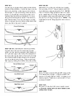
Kasco marine 1400JFL Скачать руководство пользователя страница 12


STEP SIX 

Use the ropes to position the Fountain in the desired 
location in the pond/lake.  Anchor the ropes or secure 
them to the shoreline so the ropes are free of slack, 
but not tight.  To prevent twisting of the unit due to 
torque, you should place the anchor at least 3 feet 
from the float for each foot of depth (Ex. A 3 foot 
deep pond would require an anchor 9 feet horizon-
tally from the float.)  For ease of removal, you may 
choose to keep at least one anchor within reach from 
shore, just below the water’s surface. 

STEP SEVEN 

(ALTERNATE INSTALLATION) 

In ponds where the water level fluctuates signifi-
cantly, you may need to suspend a small weight (12” 
of 1” galvanize pipe works well) at the mid-point of 
the rope to take up any slack as the water level drops.  
The weight should be light enough so the Fountain 
can rise as the water level rises.  This can also help 
hide ropes by sinking them further below the surface. 

STEP EIGHT 

Install the C-25 on the post with the power supply.  
Use up to three #10 x 1” long or longer screws and 
the molded screw placements on the C-25.  

NOTE:  

The C-25 must be hung upright in order to be water-
proof.  Install the Low Voltage Transformer (if lights 
are included) on the same pole below the C-25 with 
the one #6 x 3/4” long or longer screw.  

NOTE:  

The 

Transformer must be hung upright in order to be wa-
terproof. 


STEP NINE 

Set C-25 Timer to desired ON and OFF times per the 
C-25 Instructions on page 7.  Plug the 1400JF cord 
into the C-25 outlet labeled “UNIT”.  If lights are in-
cluded, plug the Transformer cord into the C-25 out-
let labeled “LIGHT”. 


STEP TEN 

Plug the C-25 into the 120V power supply on post 
and 

ENJOY YOUR NEW KASCO 1400JF AER-

ATING FOUNTAIN.


12 

Содержание 1400JFL

Страница 1: ...er s Instructions 3 III Warranty Warranty Claim Return Policy 4 5 IV Maintenance Recommendations 6 V C 25 Instructions 7 VI Parts Included Tools Needed 8 VII Nozzle Options Pattern Sizes 9 VIII Replac...

Страница 2: ...ith the electrical equipment plugged in and or in operation All Kasco equipment is ETL approved to UL and CSA stan dards for safety in water and all fountain models included control panels with GFI pr...

Страница 3: ...m the date of purchase See Warranty Warranty Claim Return Policy on pages 4 5 Please fill out the enclosed ad dressed Warranty Card and mail it to Kasco Marine to start your warranty coverage You may...

Страница 4: ...ent Cuts in the power cord are not covered under warranty The Fountain is damaged by unauthorized tampering Warranty Claim Procedure Check the eight digit serial number printed either on the black cov...

Страница 5: ...ight within the continental United States Other Repairs Most failed equipment can be repaired at substantially lower costs than replacement with new Please ship ac cording to the instructions in the p...

Страница 6: ...hould be removed from the water to protect them from the expansion pressure of the ice In many areas fountains will keep some amount of ice open through the winter However when the water is thrust int...

Страница 7: ...TON MUST BE PUSHED FIRMLY AND FULLY INTO PLACE UNTIL IT LOCKS AND RE MAINS DEPRESSED AFTER PRESSURE HAS BEEN REMOVED DANGER IF RESET BUTTON DOES NOT POP OUT IF TEST LAMP REMAINS LIT WHEN RESET BUTTON...

Страница 8: ...s and a mooring rope 1 TOOLS SUPPLIES NEEDED A Anchors or stakes for installing unit 2 B Flat Head Screw Driver C Philips head screw driver for mounting C 25 and Transformer if lights are included and...

Страница 9: ...mes installed on unit Condor Produces a two tiered arch of water with an inner arch 4 feet high by 4 feet in diameter and an outer arch 2 feet high by 10 feet in diameter To use this nozzle you must h...

Страница 10: ...LOCK WASHER 1 4 3 12 146400 6 X 3 4 LONG FILLISTER HEAD SS 4 13 144100 SCREW SELF TAPPING 1 14 142212 NOZZLE 1400 SERIES 1 23 140925 PROP 1400 1 24 443154 1 4 20 x 3 8 FILLISTER 1 25 181625 TRANSFORM...

Страница 11: ...Phillips Head Screw and tighten until snug Diagram A If either the Eagle s Nest or Hawk s Nest patterns are desired you must remove both the Osprey Nozzle and the Upper Pump Housing Re move the Osprey...

Страница 12: ...water level drops The weight should be light enough so the Fountain can rise as the water level rises This can also help hide ropes by sinking them further below the surface STEP EIGHT Install the C...

Страница 13: ...ou are noticing these symptoms the unit should be unplugged immediately because the Thermal Overload will continue to turn on and off until it burns out and damages the motor The unit should be unplug...

Страница 14: ...ister your fountain online at www kascomarine com solutions_warranty_registration htm Also fill in the information below and keep for your records Model Ex 1400JF _______________________________ Seria...

Отзывы: