


ASSEMBLY AND INSTALLATION INSTRUCTIONS
STEP ONE
Remove all contents from package and place on a
clean, flat surface. Inspect the shipment for any dam-
ages. If damages are found, immediately notify your
carrier and your Kasco Marine, Inc. representative.
Next, cross reference the parts included in the ship-
ment with the Parts Included sheet in this manual on
page 8. Make sure you have all the parts needed. If
any shortages are found, contact your Kasco repre-
sentative immediately.
STEP TWO
Locate and unwind the two braided nylon ropes in-
cluded with the shipment. There are two molded
Rope Holes on opposite sides of the float attached to
the fountain assembly. Tie one end of a rope to one
rope hole with a secure knot. Be sure not to leave too
much of a tail after the knot. Repeat with the other
rope on the other Rope Hole.
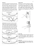
STEP THREE
Locate the 5 nozzles included with the shipment (the
Osprey nozzle is already installed on the fountain,
along with the Upper Pump Housing). Using the
Nozzle Options diagram on page 9, determine which
pattern is desired and the corresponding nozzle. If
the Condor or Falcon patterns are desired, you must
remove the Osprey Nozzle by removing the 1” Self
Tapping Phillips Head Screw. Replace the nozzle
with either the Condor or Falcon, re-insert the 1” Self
Tapping Phillips Head Screw and tighten until snug
(Diagram A). If either the Eagle’s Nest or Hawk’s
Nest patterns are desired, you must remove both the
Osprey Nozzle and the Upper Pump Housing. Re-
move the Osprey nozzle first as above.
Second, remove the 4 Upper Pump Housing screws
and pull the Upper Pump Housing up. Finally, re-
move the 3/8” Fillister head, plastic set screw in the
top of the 4 Blade Prop. Place a slight amount of
pressure on the new nozzle when in place and tighten
the 1/4-20 x 7/8” Fillister head screw until snug. Do
not over tighten. (Diagram B)
A
B
STEP FOUR
Install the Fountain into the pond/lake in at least 12”
of water so the unit is floating freely. Support the
weight of the unit with the ropes and/or the float
while setting it into the water, DO NOT LIFT BY
THE CORD. Use the nylon tie to secure both cords
and an adjacent mooring rope together about 1 foot
from the float to prevent twisting or getting caught in
the unit. Secure the ends of the cords to the post at
the power supply so the ends do not get dragged into
the water.
STEP FIVE
Determine how to anchor or secure the unit in the
pond. You may want to use weights at the end of
each rope (cinder blocks work well) and sink them to
the bottom or secure the ropes to the shoreline by ty-
ing them to a stake or placing a rock on top of the
ropes.
1” Self Tapping
Phillips Head
Screw
#6 x 3/4” Fillister
Head Upper Pump
Housing Screws
Upper Pump
Housing
Osprey Nozzle
11
1/4 –20 x 7/8”
Fillister Head
Screw
Eagle’s Nest
Nozzle


