72
APPENDIX
WTC 600 LP / MP
Service Handbook 08.2004
2
Installation/Start-up
2.1
Basic Requirements for System Installation
The following remarks have to be observed during installation and connection of the RO 1000
unit:
– The connected consumers must not exceed the max. admissible loads of the circuit outputs
as well as the total output of the unit (see item 5) (in case of inductive loads, the phase angles
have to be taken into account).
– All inductive consumers (valves, motors, contactors, transformers) of the unit have to be
provided with suitable interference suppressors (RC element, varistor, diode)
– Should other devices with a high mains-borne interference level be installed in the
surroundings of the control system, suitable external interference suppressors (line filters)
have to be installed at the supply voltage input.
– The clamps must not be actuated with too much force.
– The screw-less terminal clamps are suitable for single-core and fine core conductors (without
sleeves) of up to 0.5mm2 (for sensor and analog output terminals) and up to 2.5 mm2
respectively (all further terminals). According to the manufacturer's instructions it is not
necessary to use core sleeves.
– All assembly activities have to be done in accordance with the corresponding VDE
regulations.
2.2
Start-up
For the first start-up of the unit after its installation, the below-mentioned steps have to be carried
out in the given order. Should the control system not operate in the described manner or if
other malfunctions are discovered, the electric supply has to be interrupted immediately
(and repaired by the manufacturer).
1.
Install control and fix all terminal clamps. It has to be taken into account that the softener
output is not protected by fuses. A short-circuit at this output may therefore destroy the
conductor lines.
2.
Switch on mains supply voltage è after at most 5 sec a text has to be displayed on the LC
display (otherwise switch off è repair).
3.
Carry out diagnostic program (see item 3.3) and test all inputs and outputs of the control unit.
Should the fuse on the pc-board become active, one of the valve outputs is short-circuited.
4.
Set operating modes and parameters (see item 4).
5.
Calibrate sensors (see item 4.4.2).
Содержание WATERCLEAN 600 CD
Страница 1: ...Service Handbook 5 905 521 08 2004 Waterclean 600 CD LP MP PI 1 024...
Страница 6: ...WTC 600 LP MP 6 Service Handbook 08 2004...
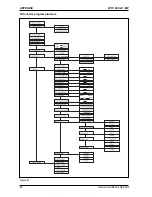
Страница 64: ...64 APPENDIX WTC 600 LP MP Service Handbook 08 2004 RO control program structure Figure21...
Страница 65: ...65 WTC 600 LP MP APPENDIX Service Handbook 08 2004...
Страница 66: ...66 APPENDIX WTC 600 LP MP Service Handbook 08 2004 RO 1000 Manual Control System RO 1000 MANUAL...


