background image

Service Handbook

5.905-521

08.2004

Waterclean 600 CD,

LP/MP, PI

1.024-...

Содержание WATERCLEAN 600 CD

Страница 1: ...Service Handbook 5 905 521 08 2004 Waterclean 600 CD LP MP PI 1 024...

Страница 2: ...hole product range In addition we compile service manuals for the main units which can be used as instructions to start with and as a reference work later on In addition we issue regular Service Infor...

Страница 3: ...lter 15 2 3 1 4 RO System Pump and Fine Filter 15 2 3 1 5 Control Panel and Display 15 2 3 1 6 Anti Scalant and Post Chlorination 15 2 3 1 7 Pressure increase Pump 16 2 3 2 Safety Installations 16 2 3...

Страница 4: ...4 Programming 33 3 4 3 Starting Operation of the RO System 35 3 4 3 1 Operating Levels and Passwords 35 3 4 3 2 Menu Selection 35 3 4 3 3 Selection of an Option 35 3 4 3 4 Selecting Several Arguments...

Страница 5: ...d 55 4 5 Malfunction Cause and Corrective Action 57 4 5 1 Metering Station LED and Indicator LEDs at the Switch Cabinet 57 4 5 2 Malfunction Indication at the Operating Panel 58 4 5 3 Malfunctions of...

Страница 6: ...WTC 600 LP MP 6 Service Handbook 08 2004...

Страница 7: ...the death s head symbol Following this symbol are recommendations or tips which make working easier and provide for secure operation Following this symbol are recommendations or tips which make workin...

Страница 8: ...t protective equipment goggles gloves and when dust is produced breathing mask protection with a filter Keep an eye wash bottle small readily available Provide for adequate room ventilation and a wash...

Страница 9: ...onductor protection class I 1 5 General installation notes Only use food safe components and resources on the drinking water side Pay special attention to hygienic cleanliness when installing drinking...

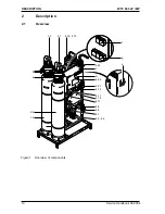
Страница 10: ...ESCRIPTION WTC 600 LP MP Service Handbook 08 2004 2 Description 2 1 Overview Figure 1 Overview of components 1 3 e 2 2 a b 1 2 2 1 4 12 4 13 f g 4 23 c d 4 24 4 21 4 14 4 11 4 15 4 17 4 4 4 3 4 7 4 5...

Страница 11: ...ump a Media filter control b Control activated carbon filter c Control cabinet d Manual automatic rotary switch e Master switch f Media and activated charcoal plug sockets g Power outlets 3x for meter...

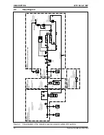
Страница 12: ...12 DESCRIPTION WTC 600 LP MP Service Handbook 08 2004 2 2 Flow Diagram Figure 2 Flow diagram of the complete reverse osmosis system RO system...

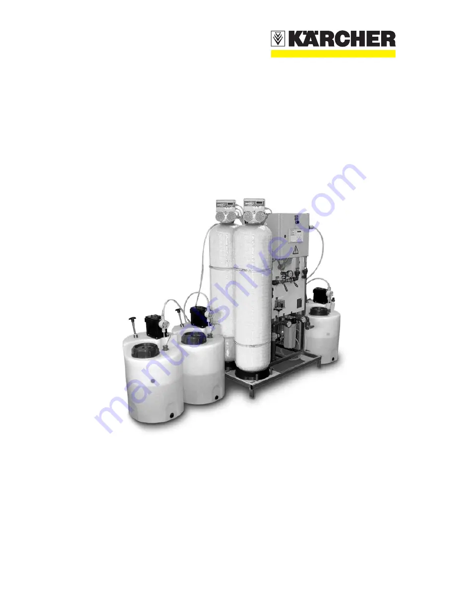
Страница 13: ...ter Media filter and flocculation module 1 Activated carbon filter module 2 Reverse osmosis system module 4 Pressure increase pump module 5 Metering stations The RO system is designed for stationary u...

Страница 14: ...filtered water through two RO filters 4 1 which are connected in series 2 3 1 5 Control Panel and Display The control panel is used for data input in the control and as LED indicator for the operatin...

Страница 15: ...ency stop switch 7 4 main switch is located on the side of the switch box RC Protective Switch RC protective switch external i 30 mA Circuit Breaker Automatic circuit breaker 7 3 10 A for power limita...

Страница 16: ...tion of an error acknowledgement only in case of pre selection Vw acknowledgement by actuating the ESC key button no further operating by the operator is possible this is to protect the control system...

Страница 17: ...er Switch cabinet IP44 Pump and valves IP44 Metering pump IP44 Power outlets plug inserted IP44 Minimum temperature of untreated water 5 C Maximum temperature of untreated wate 35 C Reference temperat...

Страница 18: ...r diameter d25 Concentrate threaded connection hose nozzle Outer diameter d25 Outlet for flushing water HT pipe d50 Canal connection supplied by customer DN 50 Hydraulic Data Maximum allowable flow ra...

Страница 19: ...Sterilization agen RM 852 6 291 772 0 RM 5000 hardness stabilization 6 290 991 0 RM 5001 Flockulents 10 l 6 294 703 0 RM 5001 Flockulents 60 l 6 294 716 0 Table 5 K rcher Original Products 2 5 2 Clea...

Страница 20: ...lectrical system SLP 3 3 2 Table 8 Assembly work to be carried out upon starting operation Starting Operation Chapter Establishing the untreated water supply 2 2 Manually actuating the sand filter bac...

Страница 21: ...dry Use the prescribed system yield 50 or 75 and the water analysis to determine each of the chemical quantities for a 30 litre metering solution according to Chap 3 2 to 3 5 add to the tanks and mix...

Страница 22: ...se values are entered in the customer s operating instructions Calculation example Yield 75 Iron Fe 1 0 mg l Manganese Mn 1 0 mg l Ammonium NH4 0 2 mg l Iron content 1 0 x 0 4 0 4 Manganese content 1...

Страница 23: ...l design is necessary If this design is not possible the following setting is recommended 5 mg l RM5000 and 50 yield until the precise design is available Range of Water Hardness Antiscalant mg l Mete...

Страница 24: ...s Example Chlorine content 1 2 mg l RM 852 4 x 32 ml 128 ml Chlorinated Lime 4 x 17 68 ml 3 2 5 Flocculation Agent The exact demand in flocculents can only be determined by test Therefore a test solut...

Страница 25: ...t more test solution if not successful repeat with less test solution If analysis is not possible on the spot take out 2 litres of test solution and store in refrigerator at ca 4 C until analysis Cool...

Страница 26: ...led without mechanical tension Drinking water line to be installed with free run out and no further shut off devices Backwashing line to be installed with steady drop under no circumstances inclined u...

Страница 27: ...means of preservation to the screwed connection above the Antiscalant 10 1 metering line as well as to the drinking water connection 11 4 and to the concentrate connection 11 3 These are to be removed...

Страница 28: ...float switch must be inserted in the metering pump unit Figure12 Alarm output and digital input of the metering pumps Alarm output empty alarm Digital input release For connection of the control cable...

Страница 29: ...tiscalant Alarm output 12 1 not required white blue Empty signal brown 16 black 17 Digital input 12 2 Release brown 10 blue 11 not required white black Post chlorination Alarm output 12 1 not required...

Страница 30: ...in existence or have confirmed in writing 3 4 Starting Operation Operation of the individual equipment components is started in the following sequence Fill the preliminary filter and start operation b...

Страница 31: ...rs must be backwashed For this the complete system is to be connected hydraulically and electrically and to be switched on at the main switch The reverse osmosis system must be in the Switched Off ope...

Страница 32: ...ming of time steps ADVANCE 1 For changing of parameters during proggramming 2 Calls up the diagnosis see Table 24 press for 10 sec MANUAL REGEN 1 Activates a manual regeneration 2 Runs step by step th...

Страница 33: ...Covered pushbutton 4C03 Initial filtration 3 minutes 15 Covered pushbutton 4d10 Leave programming mode Table 18 Programming table1 for media filter and activated carbon filter 1 For changing of any gi...

Страница 34: ...tion Technician password ESC ESC To enter a password the respective key sequence must be entered in the normal level within one minute For settings and menus of the RO 1000 control system see figure 2...

Страница 35: ...ressing the RETURN pushbutton the input can be cancelled by pressing the ESC pushbutton 3 4 3 6 Acknowledging Data Inputs To avoid input errors acknowledgments are required at various menu locations T...

Страница 36: ...ting mode Operating mode Operation Operating mode Switched off Execute no yes Execute no yes 1 Error ack 2 Operating mode Operating mode Switched off System in disinfection operating mode Set the conc...

Страница 37: ...ll changes of the settings to the system the following values may not be exceeded under any circumstances Maximum pump pressure 21 bar MP or 14 bar LP Drinking water amount 650 liters per hour maximum...

Страница 38: ...utton Use the keys to set the limiting value upper limiting value of the drinking water conductivity 20 of the untreated water conductivity value Use the key to change to warn value Use keys to set th...

Страница 39: ...are with Chapter 3 4 3 1 RO 1000 V 01 34 Switched off RO 1000 V 01 34 production on hours meter 1111 h 11 min W Temp 12 3 C perm 12 S cm Figure16 User indication in normal operation 1 ackn failure 2 o...

Страница 40: ...does not produce during regeneration flushing The regeneration LED lights at the operating panel Indication Forced stop on the display Cause One of the preliminary filters is being cleaned 3 The syst...

Страница 41: ...tem is switched off e g when putting out of operation for extended periods For out of operation periods exceeding 14 days the equipment must be conserved see Chapter 4 4 4 Enter user password for this...

Страница 42: ...ndication Press the pushbutton Indication operation mode Desinfection 1 ackn failure 2 operat mode operation mode OPERATION operation mode STOP are you sure no yes are you sure no yes 1 ackn failure 2...

Страница 43: ...g Station WTC 600 CD Every 4 weeks Clean the inside of the metering tank and thoroughly rinse with chlorine free drinking water When working on the metering head or on the connections and lines wear p...

Страница 44: ...smosis Module RO Module 4 3 1 RO Filter Replacement The RO filters are to be replaced when cleaning and disinfection as a measure to increase the capacity have been without success Filter replacement...

Страница 45: ...m the original values cf operating certificate are indicators for the need for cleaning or disinfecting the system The WTC 600 service kit 2 901 044 0 is intended for cleaning the WTC 600 Apart from t...

Страница 46: ...e 10 Check valve 11 Concentrate control valve 12 Flowmeter concentrate 13 Electrical control system 14 Drinking water to the flushing tank 15 Concentrate to the flushing tank 16 Flushing tank 17 Sampl...

Страница 47: ...ed the concentrate adaptor and connection hose from the concentrate outlet 20 12 to the flushing tank Unplug the earthing contact plugs of the metering pumps Switch the flushing pump on 4 Switch the s...

Страница 48: ...regulations 6 Connect the soft water supply to the RO equipment again guide drinking water and concentrate outlet to the canal The drinking water and concentrate line must not have contact with the c...

Страница 49: ...leaning solution during cleaning 15 C End the cleaning when a change of the pH value can no longer be detected If the cleaning solution is strongly soiled it should be neutralized and rejected Continu...

Страница 50: ...aning solutions for alkaline cleaning Neutralise by adding RM Vaporapid bio descaling acid 6 290 239 until the pH value is approx 7 4 4 4 Conserving 4 4 4 1 Drain the metering station and flush Initia...

Страница 51: ...r and connection hose from the concentrate outlet 20 12 to the flushing tank Switch on the flushing pump 3 Switch system to disinfection operating mode and adjust water pressure to 2 bar manometer 4 7...

Страница 52: ...vated carbon filter 4 Attach a connection hose to this hose nozzle and screw tight with a hose clamp 5 Fix the other end of the connection hose to the filter control heads 6 Keep the untreated water s...

Страница 53: ...es apron Flushing pump Initial situation RO system set to switched off operating mode and with master switch switched on Work steps 1 Add 30 litres drinking water to the flushing tank and add 2 2 litr...

Страница 54: ...ilters does not reduce despite flushing the filter medium cf Chap 4 the filter material must be replaced Auxiliaries Wet dry vacuum NT 602 ECO 1 408 151 0 4 metal suction pipes 0 5m 6 902 050 0 Remove...

Страница 55: ...aking the pipe Firmly push the metal pipes together or secure with thin adhesive tape 5 Clean the pressure tank with clean water and check for internal damage 6 Fill with new filter material cf Chap 3...

Страница 56: ...2 3 1 5 LED lights drinking water tank tank full the equipment 3 3 2 4 has switched automatically switches on again Switch defective Check switch replace if necessary Table27 Malfunction indications...

Страница 57: ...nsure supply pressure high pump is not to the pump mains self priming supply submerged pump Supply pressure of Flow rate through see 4 5 4 the reverse preliminary filter osmosis too low too low Differ...

Страница 58: ...ner is draw in fittings Replace constant for suction line days Suction line Flush or replace clogged suction line Crystals debris in Clean valves 4 2 the valves metering head Membrane torn or Replace...

Страница 59: ...sand Small particles Install preliminary 4 1 pressure of filter turbid come through treatment fine filter quickly exceeds 1 bar Filtrate of the Small particles Check sand filter 4 1 activated carbon...

Страница 60: ...iner Weekly Check filling and refill 3 2 Media filter activated carbon Weekly Automatic backwashing check 3 4 2 4 filter operation meter Control sheet Weekly Fill out Appendix Metering stations Every...

Страница 61: ...f used up filters since last service Reverse osmosis Assess general condition Data input according to daily operating log and operational start up record Leakage tightness of the complete equipment in...

Страница 62: ...t 1 s t Press start up delay 9 9 s t pressure available 60 s t discont flushing 10 min or longer depending on specifications t flushing interval 24 h or less depending on specifications t Concentrate...

Страница 63: ...t up delay 9 9 s t pressure available 60 s t discont flushing 10 min or longer depending on specifications t flushing interval 24 h or less depending on specifications t Concentrate displacement 01 mi...

Страница 64: ...64 APPENDIX WTC 600 LP MP Service Handbook 08 2004 RO control program structure Figure21...

Страница 65: ...65 WTC 600 LP MP APPENDIX Service Handbook 08 2004...

Страница 66: ...66 APPENDIX WTC 600 LP MP Service Handbook 08 2004 RO 1000 Manual Control System RO 1000 MANUAL...

Страница 67: ...sic Requirements 72 2 2 Start up 72 2 3 Function of Terminals 73 3 Operational Scope 74 79 3 1 Operating Settings 74 3 2 Operating Parameters 75 3 3 Operating Modes 76 77 3 4 Operating Conditions 78 3...

Страница 68: ...8 2004 Contents 4 3 Operating Levels 83 4 3 1 Normal Level 83 4 3 2 User Level 83 4 3 3 Technician s Level 83 4 4 Menu Structure 85 4 4 1 Main Menu 86 4 4 2 Calibration Menu 87 4 4 3 Setting Menu 88 4...

Страница 69: ...on is accepted 1 2 Scope of Application The RO 1000 system is a control system for reverse osmosis units of different sizes Its technical features are Microprocessor control with liquid crystal text d...

Страница 70: ...issible load of the circuit outputs as well as the total admissible load of the unit see item 5 must not be exceeded 1 4 Safety Instructions The following safety instructions are imperative Diagnosis...

Страница 71: ...capitals underligned capitals underligned STOP ON PRODUCTION DISPOSAL MOTOR FAILURE FORCED STOP The following abbreviations will be used Cy perm permeate conductivity t perm permeate temperature Remar...

Страница 72: ...ensor and analog output terminals and up to 2 5 mm2 respectively all further terminals According to the manufacturer s instructions it is not necessary to use core sleeves All assembly activities have...

Страница 73: ...conductor outlet valve closer outlet valve opening contact 1000 VA 2 5 mm 2 5 mm 2 5 mm 17 18 19 MV3 PE MV3 N MV3 Ls concentrate valve protective cond concentrate valve neutral cond concentrate valve...

Страница 74: ...witch off ps acknowledgment function Prelesect if acknowledgment of failures is possible in the normal level without password or only in the user technician level with password right of access technic...

Страница 75: ...defined for t delay aaLIM right of access user technician possible setting 0 5 50 S cm 10 S cm Attention the set value must be lower than LIM t delay LIM function Time delay for wrong permeate limit...

Страница 76: ...after which the unit passes to PRODUCTION if the value drops below LIM right of access technician possible setting 0 999s 5s Attention the set value must be less than t max disposal Pay attention to u...

Страница 77: ...e etc are displayed one after the other rolling Failures are registered processed and displayed DISINFECTION The control system does not carry out any production process but INLET VALVE OUTLET VALVE a...

Страница 78: ...itions When the unit is in OPERATION the control system performs one of the seven possible operating conditions The following diagram shows the various conditions as well as the reasons for status cha...

Страница 79: ...ches off LACK OF PRESSURE PRESSURE SWITCH active Unit switches off MAINTENANCE When the preset maintenance interval is over the LED display OPERATION starts to flash but only if control system is in t...

Страница 80: ...mediately after having the control system switched on the reason is an internal system failure see item 3 5 DISINFECTION Active if the control system is in the operating mode DISINFECTION DISPOSAL Act...

Страница 81: ...t means it always displays a two line section window of the whole menu If a function or a menu point has to be called in the desired menu point has to be selected first using the keys If the menu cons...

Страница 82: ...upper display line The current value is displayed in the lower line A flashing block cursor always marks the figure which can be modified this modification new setting can be achieved with the keys C...

Страница 83: ...el The technician s level is a extended user level It allows to carry out the functions of the user level to manipulate all operating settings parameters and to fulfil a hardware test by means of a sp...

Страница 84: ...nction does not correspond to the display of measured values the control system automatically returns to the normal level for safety reasons 4 3 3 Technician s level The technician s level is an expan...

Страница 85: ...85 WTC 600 LP MP APPENDIX Service Handbook 08 2004 4 4 Menu structure The menu structure of the user surface is shown below Access to the main menu is achieved by entering a pass word see item 4 2 1...

Страница 86: ...e keys 4 Temp permeate Permanent display of current permeat temperature To leave this menu point press one of the keys 5 Hour meter Calling in display of the operating hours meter 6 Cy limits Numerica...

Страница 87: ...he current permeate conductivity has to be determined by means of a standard meter and this value has to be entered by numerical editing The entered value is equated with the current conductivity afte...

Страница 88: ...types valve with open rest pos opener 15 ps language Selection of ps language 16 system reset As soon as this function is called in and acknowledged the internal hours meter will be deleted set to 0 4...

Страница 89: ...V Hz VA ambient temperature range operation ambient temperature range storage relative air humidity 0 10 15 50 70 85 C C conductivity range accuraCy of measurement ref to range end value without sens...

Страница 90: ...treated Water Operating Data Drinking Water Malfunctions Remarks Hard ness dH Temper ature C Conduct ing capacity S cm Operat ing hours h Pressure ahead of fine filter bar Pump pressure bar Concen tra...

Страница 91: ...quipment 26 Connections Valves and Indicators 26 Conserve the RO system 50 Conserving 50 Consumption Materials 19 Control activated carbon filter 11 Control cabinet 11 Control Panel and Display 14 Con...

Страница 92: ...on 34 Menu structure 85 Metering Amounts and Mixing of the Post Chlorinati 24 Metering Station 28 30 Metering Station LED and Indicator LEDs at the Swi 56 Metering Station WTC 600 CD 43 Microfuses 16...

Страница 93: ...14 S Safety Installations 15 Safety Instructions 70 Sampling valve for drinking water 46 Sampling valve for untreated water 46 Scope of Application 69 Selecting Several Arguments at the Same 35 Selec...

Отзывы: