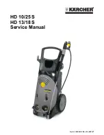
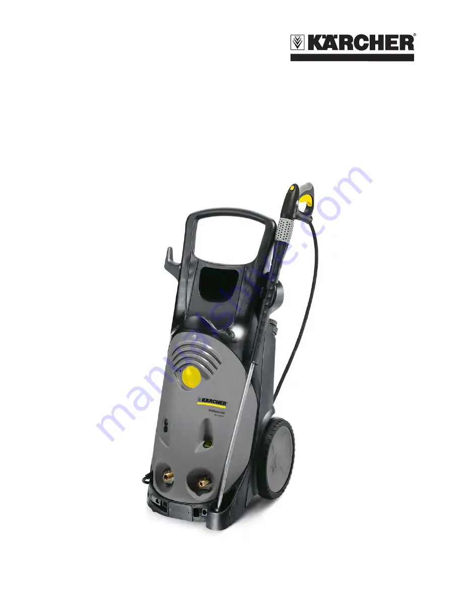
manualshive.com logo in svg
background image


English 

5.905-945.0 Rev. 00 (06/15)

 1

HD 10/25 S
HD 13/18 S
Service Manual

Содержание HD 10/25 S VEX

Страница 1: ...English 5 905 945 0 Rev 00 06 15 1 HD 10 25 S HD 13 18 S Service Manual...

Страница 2: ...12 6 4 Hand spraygun 15 6 5 Pressure and volume regulation 16 6 6 Triple nozzle 17 6 7 Electronics system 18 6 7 1 Pump monitoring 18 6 7 2 Leakage monitoring 18 6 7 3 Motor protection 18 6 7 4 Displa...

Страница 3: ...ing and duplication of texts and diagrams as well as third party access to this information is permitted only with the explicit permission of the company Alfred K rcher GmbH Co KG P O Box 160 D 71349...

Страница 4: ...dditional contactor the service life of the pressure switch is extended significantly Automatic safety switch off after 30 minutes of non op eration Automatic safety switch off in case of leakage Prot...

Страница 5: ...ture 5 Serial number 6 Nozzle size 7 Address of manufacturer 8 Bar code Contains part and serial number 9 Max feed temperature 10 Typical operating weight 11 Max operating over pressure 12 Type of pro...

Страница 6: ...wer switch Q1 S1 6 Operating display LED D1 7 Screw of the cover 8 Storage power cord 9 Transport handle 10 Power press regulator Pressure quantity regulation 11 Lock trigger gun 12 Trigger gun 13 Lev...

Страница 7: ...without hose drum 1 Storage power cord 2 Storage dirt grinder 3 Storage triple nozzle 4 Kick plate to tilt the appliance 5 Wheel 6 Storage compartment for accessories 7 Detergent tank lid Dosing valve...

Страница 8: ...Wheel 6 Kick plate to tilt the appliance 7 Storage compartment for accessories 8 Detergent tank lid Dosing valve 9 Transport handle Unit without hose drum 5 3 View from below 1 Rubber feet 2 Screw plu...

Страница 9: ...ater supply 6 Pump head 7 Mains connection 8 High pressure hose 5 4 Front view without cover 1 Motor M1 2 Manometer 3 Detergent connection with check valve 4 Detergent injector 5 High pressure connect...

Страница 10: ...rgent injector 6 Bypass valve 7 Duct high pressure hose 8 Overflow valve 9 Water connection 10 Mains connection 11 Water filter 12 Oil tank 13 Oil container lid 14 Electronics system 15 Power switch Q...

Страница 11: ...e retaining valve 13 Suction valve 14 Pressure valve 15 Locking screw for pressure valve 16 High pressure seal 17 Low pressure seal 18 Oil seal 19 Plunger 20 Holding plate of piston spring 21 Slide sh...

Страница 12: ...nnecting boring to the suction chamber The manometer displays the working pressure in the pres sure room But due to the affect of the control pressure injector there is less pressure in the connecting...

Страница 13: ...the rod slightly pushes the ball out of its seat so that a part of the flow rate flows to the suction chamber The pressure switch is slightly pushed to the right due to the increased pressure in the...

Страница 14: ...retaining valve closes This way the entire system pressure is locked between the trigger gun and the pressure retaining valve When the gun is opened again the pressure in the system decreases rapidly...

Страница 15: ...manual lever is actuated the valve in the node piece opens and the water can flow from the hose through the gun into the spray lance Note The node piece cannot be repaired and must be replaced as a c...

Страница 16: ...he high pressure chan nel The ceramic disc is rigidly connected with the connection of the trigger gun The ceramic disc is connected to the ro tary switch and therefore adjustable Offset holes in the...

Страница 17: ...ce while the hand lever of the trigger gun is released In the process the valve ball rolls in front of one of the two nozzles and closes it To adjust the point jet hold the trigger gun in the initial...

Страница 18: ...y means of the DIP switch see circuit diagram If one phase fails in case of excessive temperature low voltage or in case of a voltage difference between 2 phas es 50 V the immediate switch off and loc...

Страница 19: ...akes place by switching on and off the power switch 6 7 5 Reset 6 7 6 Setting the DIP switches ON OFF 1 1 phase device 3 phase device 2 Do not use No after run of the pump 3 Leakage monitoring No moni...

Страница 20: ...ns low In low pressure operation the pressure spring presses the piston onto the valve seat and closes the water flow The entire water volume flows through the nozzle insert and the detergent is sucti...

Страница 21: ...pening pressure is reached see technical data Secure the adjustment nut by means of the lock nut Switch the appliance off and remove all pressure by opening the gun Connect the test manometer with hig...

Страница 22: ...ull the high pressure hose off the connection piece 1 Screws 2 Hose drum Unscrew the screws Remove the hose reel 1 High pressure hose 2 Safety clip 3 High pressure outlet 4 Hose drum Completely unwind...

Страница 23: ...e hose out of the high pressure outlet 1 Crank Remove the crank from the hose reel straightly 1 Holder hose reel 2 Screws 3 Hose drum Unscrew the screws Remove half shells of the hose reel 1 Node piec...

Страница 24: ...905 945 0 Rev 00 06 15 1 Seal screw 2 Node piece 3 Axle 4 O rings Remove O rings Check axle and connection piece for signs of wear Installation information Replace the O rings Grease the O rings Greas...

Страница 25: ...ce Check adjust replace overflow valve Device turns on and off while hand spray gun is closed Tightness of system Check the trigger gun and the O rings on the high pressure hose for leaks replace Pres...

Страница 26: ...t impedance Ohm 0 145 j0 090 Extension cable 10 m mm2 2 5 Extension cord 30 m mm2 4 Water connection Max feed temperature C 60 Min feed volume l h l min 1200 20 1400 23 3 Suck height from open contain...

Страница 27: ...re seal Piston diameter 20mm 5 901 055 0 Installation sleeve high pressure seal Piston diameter 20 mm and 22 mm 5 901 136 0 Installation mandrel high pressure gasket Piston diameter 22mm 5 901 064 0 I...

Страница 28: ...ish 5 905 945 0 Rev 00 06 15 Test manometer for working pressure 4 742 025 0 Installation and removal tools overflow valve seat 4 901 054 0 Removal pliers pressure suction valves and water sieves 4 90...

Страница 29: ...evice please always use the cur rent circuit diagram in DISIS 11 Circuit diagram A1 Control chip B1 Pressure switch D1 Operating display LED F1 Fuse K1 Contactor M1 Motor Q1 S1 Power switch Q2 Pressur...

Страница 30: ...7 Trigger gun pressure regulator 40 Screw connection pressure valves 40 45 Screw connection pressure switch 15 17 Screw connection suction valves 5 8 Overflow valve seat 8 10 Swash plate 12 3 High pr...

Отзывы: