background image

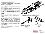
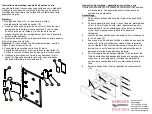
Assembly instruction for glass door lock case 

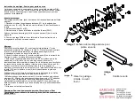
The glass door lock  is supplied pre-assembled  for left hand use and has a 
16 mm lever adapter. Please keep contact areas on the glass free of grease 
before assembling the lock. The lock case is designed for glass doors with a 
thickness of 10-13 mm and  standard holes. 
 

Before Assembly: 

Disassembly of the lockcase (for transport safety reasons the lockcase will 
be supplied  mounted): 
1.Unscrew the lever plastic guidance (13) from the stainless steel case (5) 
and (2). Remove both cross-head screws (10) from th e front face of the lock 
case. 
2.Remove the stainless steel body (5)and (2). 
3.Unscrew M5 inner hexagon screw (9) with the enclosed  Allen Key(SW 3). 
Remove  the clip base (4) and the lock boday (3) from the counterplate(8). 
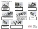
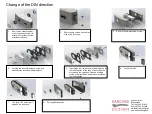
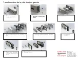
4.For use as DIN right handed, please see separate assembly instruction 
how to turn the lock body. 
 

Assembly: 

5.Insert counter plate (8) with interlayer (7) and glass protecting rings (18) 
through the galss (1). Fit lock case(3) together with interlayer (6) and rail 
clip(4) on the counter plate and screw in both counter sink screws (9). 
6.Screw lock case(3) and counter plate (8) together. Adjust circulation outline 
uniformly. 
7.Insert euro profile cylinder into euro profile lock. Use enclosed  M5 bolts(9) 
only! A longer bolt will damage the lock mechanism.  The fixing screw for the 
euro cylinder is next to the euro profile hole (Lower or upper side of the lock 
case (3)) 
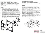
8.Attach stainless steel case (5) and screw in plastic lever guidance (13)  by 
using screw aid (10) (see image 2). Afterwards screw the stainless steel 
case (5) with the enclosed M4 screws to the lock case (3). Fix the stainless 
steel cover case (2) on the counterpart with the plastic lever guidance (13).  
9.Insert and centre up the spindle (19) that the grub screw pierces into the 
thinnest part. (see image 3). 
10. Put cover rings (16) on the plastic lever guidance (13). Attach the lever 
and make sure the spindle (13) stays centred. Screw grub screw (6) in the 
lever handle (14) by using the Allen Key (17) and tighten until the grub screw 
pierces into the spindle.


11.Functional testing 
 

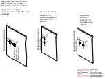
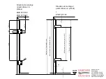
Please note: For a glass door thickness of 10 mm (e.g. Austria) you 
need to order latch ZEGS 1


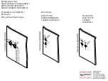
Abb. 1: 

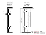
Mounting scheme of glass door lock case 

19 

Centre the 
excentrical 
spindle 

Abb. 3: 

Tighten the lever 
guidance by 
using the 
screwing aid 

Abb. 2: 

10 

22 

Karcher GmbH 
Deutschland 
Tel. +49-7264-91640 
Fax +49-7264-916440 
[email protected] 
www.karcher-design.de 

Содержание EGB101

Страница 1: ...chlossmechanismus beeinflussen kann Die Befestigungsschraube für den Profilzylinder befindet sich seitlich zum PZ Loch Unter oder Oberseite des Schlosskastens 3 8 Edelstahlgehäuse 5 aufsetzen und Kunststoff Drückerführung 13 mittels der Eindrehhilfe 10 in den Schlosskasten eindrehen Abb 2 Anschließend das Edelstahlgehäuse 5 mit den beiden beiliegenden M4 Senkschrauben am Schlosskasten 3 festschrau...

Страница 2: ...50mm für behinderten gerechte Türen ab OKFF nach DIN18024 und DIN18025 Vorderkante Glastürblatt Bohrschema für alle Glastürschlösser und Gegenkästen EGS100 EGS110Q EGS120 EGSG100 EGSG110Q EGSG120 Kompatibel zu marktüblichen Bohrungen trotz geringer Abweichungen Karcher GmbH Deutschland Tel 49 7264 91640 Fax 49 7264 916440 mail karcher design de www karcher design de ...

Страница 3: ...ation 2 teiliges Band EGB 101 102 2 Bandbezugslinie Norm 1435 OKFF 1 Bandbezugslinie Norm 241 Türhöhe Glashöhe Zargenfalzmaß 7 4 3 5 4 232 5 45 212 5 85 1349 50 Karcher GmbH Deutschland Tel 49 7264 91640 Fax 49 7264 916440 mail karcher design de www karcher design de ...

Страница 4: ...oppelseitigen Klebebandes 9 aufdrücken Vorderkante Glastürblatt 3 4 1 2 5 6 7 8 9 10 Montageanleitung 2tlg Glastürband Die Bänder sind für handelsübliche Glastüren konzipiert Halten Sie die Kontaktflächen für die Türbänder vor der Montage auf dem Glas fettfrei Montage 1 Glasschutzringe 3 in die vorgebohrten Löcher stecken 2 Türband 1 mit Zwischenlage 2 auf das Glas setzen Auf der Gegenseite Zwisch...

Страница 5: ...den Edelstahlgehäusen herausdrehen 2 Beide Kreuzschlitzschrauben an der Stirnseite des Schlosskastens entfernen 3 Edelstahlkappen abnehmen 5 Vertauschen der Komponenten Alle Einzelteile die sich auf der linken Seite des Schlosskörpers befinden werden in diesem Schritt auf der rechten Seite montiert und alle rechten Einzelteile finden ihren Platz auf der linken Seite 6 Flüsterfalle lösen Karcher Gm...

Страница 6: ...ter plate 8 together Adjust circulation outline uniformly 7 Insert euro profile cylinder into euro profile lock Use enclosed M5 bolts 9 only A longer bolt will damage the lock mechanism The fixing screw for the euro cylinder is next to the euro profile hole Lower or upper side of the lock case 3 8 Attach stainless steel case 5 and screw in plastic lever guidance 13 by using screw aid 10 see image ...

Страница 7: ...850mm adapted for the needs of disabled for OKFF Certified to DIN18024 and DIN18025 Leading edge of glass door Bore measures for all glass door locks and strike boxes EGS100 EGS110Q EGS120 EGSG100 EGSG110Q EGSG120 Compatible to usual market drillings in spite of small differences Karcher GmbH Deutschland Tel 49 7264 91640 Fax 49 7264 916440 mail karcher design de www karcher design de ...

Страница 8: ...n 2 piece hinge EGB 101 102 2 Hinge reference line Norm 1435 OKFF Hinge reference line Norm 241 Door height glass height Grip fold dimension 7 4 3 5 4 232 5 45 212 5 85 1349 50 Karcher GmbH Deutschland Tel 49 7264 91640 Fax 49 7264 916440 mail karcher design de www karcher design de ...

Страница 9: ...ter plate 6 6 Attach hinge 9 and cover 10 Vorderkante Glastürblatt 3 4 1 2 5 6 7 8 9 10 Assembly instruction of 2 piece hinge Please keep contact areas on the glass free of grease before assemblingthe hinges The hinges are designed for commercial glass doors Assembly 1 Insert glass protection rings 3 in the predrilled holes 2 Attach hinges 1 with interlayer 2 to the glass Apply inter layer 2 and c...

Страница 10: ...nce of the stainless steel case 2 Remove both screws from the front side of the lock case 3 Remove the stainless steel covers 5 Interchange the components All single pieces on the left hand side of the body of the lock will be mounted on the right hand side and all single pieces of the right hand side will be mounted on the left hand side 6 Loose the latch Karcher GmbH Deutschland Tel 49 7264 9164...

Страница 11: ...lindre profilé dans la serrure PZ et n utilisez que la vis fraisée de 5 mm 9 jointe Une vis plus longue peut influer sur la fonctionnalité du mécansime de la serure La vis de fixation pour le cylindre se trouve à coté du trou de cylindre Haut ou invers du boîtier en inox 3 8 Posez le boîtier en inox 5 et faites pivoter l axe de la poignée en plastique Vissez ensuite le boîtier en inox 5 à l aide d...

Страница 12: ...ltitiude èligilble Standard allemand 850mm au dèla de bord inférieure de porte en verre nach DIN18024 und DIN18025 Bord avant du panneau de porte en verre Perçage pour les portes en verre EGS100 EGS110Q EGS120 EGSG100 EGSG110Q EGSG120 Compatible aux perçages commerciaux malgré les différences minimales Karcher GmbH Deutschland Tel 49 7264 91640 Fax 49 7264 916440 mail karcher design de www karcher...

Страница 13: ...2 pièces EGB 101 102 2 Diréction de référence Norm 1435 OKFF 1 Diréction de référence Norm 241 Hauteur de la porte Hauteur de verre Messure du dormant de porte 7 4 3 5 4 232 5 45 212 5 85 1349 50 Karcher GmbH Deutschland Tel 49 7264 91640 Fax 49 7264 916440 mail karcher design de www karcher design de ...

Страница 14: ...e adhésive bilatérale à la contreplaque 6 Instruction de montage paumelle pour porte en verre Veuillez vous assurez que la surface en contact avec la paumelle soit bien propre Les paumelles sont conçues pour des portes en verre standard Assemblage 1 Enfoncez les anneaux de sécurité 3 dans les trous déjà percés 2 Posez la paumelle pour porte 1 avec la partie intermédiaire 2 sur la vitre De l autre ...

Страница 15: ...errure Transformation de la côté droit ou gauche 1 Enlevez les bagues en inox et en plastique du boîtier 2 Retirez les vis sur le côté de la serrure 3 Enlevez le cache 5 Echangez les éléments Montage rectoverso 6 Enlevez le pêne silencieux Karcher GmbH Deutschland Tel 49 7264 91640 Fax 49 7264 916440 mail karcher design de www karcher design de ...

Отзывы: