background image


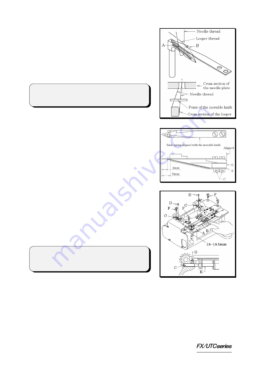
6-3 Adjusting the back spring 

To cut the needle and looper threads, the movable 
knife moves to the stationary knife with the needle 
thread hooked on cutting edge A and the looper 
thread hooked on cutting edge B while entering the 
needle thread loop (see the illustration). 
Then the looper thread is held by the stationary 
knife and the back spring. 
Position the back spring by referring to the 
illustration and secure it with screws C. 


6-4 Adjusting the stopper 

Stopper C adjust the position to which the movable 
knives protrude.    With the needle bar at the top of 
its stroke, press the center of movable knife base B 
until the movable knives touch the stopper. 
Loosen screws D.  Adjust the movable knives so 
that they touch the stopper when the distance from 
bottom surface B of the movable knife base to 
bottom surface A of the needle plate is 18~18.5mm. 
Adjustment is made by loosening screws D. 


< Note > 

End E of the cylinder rod should tightly contact left 

and right stoppers C.  Be sure to turn off the air 

when adjusting the stoppers. 

< Note > 

Adjust the back spring so that the back spring does 

not hold the needle thread after it is cut. 


5

Содержание FX/UTC Series

Страница 1: ...INSTRUCTION FX UTC MANUAL Industrial Sewing Machines First published May 1997 Fourth edition January 2006 No 050153...

Страница 2: ...Read and study this instruction manual carefully before beginning any of the procedures and save it for later use This instruction manual describes adjustments and maintenance procedures for the threa...

Страница 3: ...THE PEDAL 4 6 ADJUSTING THE THREAD TRIMMER 6 1 Position of the movable knife 4 6 2 Position of the stationary knife 4 6 3 Adjusting the back spring 5 6 4 Adjusting the stopper 5 6 5 Disassembling and...

Страница 4: ...ETECTOR Install the position detector by referring to the illustration on the right 2 CONNECTING RELAY CORDS AND AIR LINES 2 1 FX4404 Connect relay cords and air lines correctly by referring to the il...

Страница 5: ...2 2 FX4406 4412 2...

Страница 6: ...e speed when the thread trimming knife holder retracts If screw A is too loosened the knife holder will protrude too fast and then the position of the knife holder will become unstable causing cutting...

Страница 7: ...ise the presser foot while the machine stops press the pedal with heel position C 6 ADJUSTING THE THREAD TRIMMER 6 1 Position of the movable knife Adjust movable knife A so that the bottom of movable...

Страница 8: ...er C adjust the position to which the movable knives protrude With the needle bar at the top of its stroke press the center of movable knife base B until the movable knives touch the stopper Loosen sc...

Страница 9: ...assembly by following the reverse procedures of the above after performing preventive maintenance 7 ADJUSTING THE AIR WIPER The outlet of air wiper C should be positioned approximately 10mm to the rig...

Страница 10: ...r the needle and looper threads according to the distance in the illustration below To increase the amount of the thread to be released decrease distance A To decrease the amount of the thread to be r...

Страница 11: ...on the right Install the thread eyelets for the needle and looper threads according to the distance in the illustration below To increase the amount of the thread to be released decrease distance A To...

Отзывы: