background image


24

 / 

67


Connect   to   RXD,   TXD,   and   GND   only   

RS-­‐232   Settings:   


Description   

Setting   


   Baud   rate   

9600   


   Data   bits   

8   


   Parity   

None   


   Stop   bits   

1   


   Hardware   flow   control   

None   

Notes:   For   more   information   about   serial   command   lines,   see   the   chapter   of   commands.   

IP   Settings   

The   switcher   supports   IP   control,   Telnet,   UTP   and   so   on.   In   order   to   obtain   the   IP   address,       

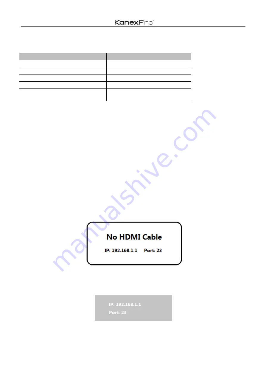
The   IP   address   and   port   number   shows   up   right   away   via   the   information   from   the   on-­‐screen   display   

(OSD)   when   connected   to   a   LAN   network       

Get   the   IP   address   and   port   number   via   the   information   from   the   OSD.   

Whether   the   switcher   is   in   single-­‐window   mode   or   in   multiple   window   modes,   IP   address   and   

port   number   can   always   be   obtained   from   Window   1.   When   there   is   no   signal,   the   following   OSD   in   

the   window   is   displayed:   


Or   when   the   picture   is   displayed,   the   IP   information   is   displayed   in   the   area   above   the   middle   of   the   

window.   


The   IP   address   is   192.168.1.1   and   the   port   number   is   23.   

Содержание HD-VTSC72-4K

Страница 1: ...1 67 4K Video Tiler Presentation Scaler Switcher Supports both models HDBT VTSC72 4K HDVTSC72 4K All rights reserved 2016 User Manual V0 5 ...

Страница 2: ...ures l Multiple inputs 4 x HDMI 2 x DisplayPort 1 x RGB YPbPr l HDMI DisplayPort source input with 4Kx2K 30Hz support l Supports MHL in the four HDMI input ports l Supports Auto Scaler in each source input l Supports different multiple window modes of quadruple windows triple windows double windows and a single window outputting to a display device through one HDMI output l Supports a lot of pre d...

Страница 3: ...ting Instructions 10 Standby Mode and Work Mode 10 Screen layout Configuration 11 Single Window 13 Double Windows 14 Triple Windows 15 Quadruple Windows 16 Output Resolutions 18 Audio Settings 19 Audio Input Select 19 Audio Output Instructions 20 OSD Setting Instructions 20 Advanced Settings 23 RS232 Settings 23 IP Setting 24 General Control 25 Advanced Control 28 Basis EDID Management 32 Advanced...

Страница 4: ...upload and Download 44 EDID Names 45 EDID commands list 45 WEB Setting 52 General Settings 53 Advanced Settings 56 EDID 62 Network 64 Other 65 Factory Reset Button 65 F W Update Guide 65 Electrical Parameters 65 ...

Страница 5: ...n and Indicator Press the buttons 1 4 indicating the corresponding windows are selected The indicators mean whether this window is effective 5 Video Window Mode Button and Indicator Video window mode selection single window double windows triple windows and quadruple windows The indicators mean whether this window is effective 6 Output Resolution Button and Indicator Selects the related resolution...

Страница 6: ...t to an HD or 4K displays 5 Analog audio input 1 7 7 channel stereo analog audio input Connect a 3 5mm mini stereo cable from the Line Out jack on the audio source to this jack 6 HDMI input 1 4 Connect up to four Hi Def sources to these inputs using HDMI cables 7 DisplayPort input 1 2 Connect up to two Hi Def sources to these inputs using DisplayPort cables 8 RGB YPbPr input Connect up to Hi Def s...

Страница 7: ...ess 1 7 buttons to select the corresponding window for select video input 4 Screen Layout Press this buttons to select Single mode Double mode TRIPLE mode and Quadruple mode 5 Audio Press this button and then press the 1 7 buttons to select the corresponding audio input 6 Mute Press this button to Mute or Unmute the Multiviewer Switcher audio output 7 Resolution Press this button to change the Mul...

Страница 8: ...our 4K or HD HDMI sources to the input ports HDMI 1 HDMI 4 Connect up to two 4K or HD DisplayPort sources to the input ports DISPLAYPORT 5 DISPLAYPORT 6 Connect up to one Hi Def VGA or YPbPr sources to the input ports RGB YPbPr on the Multiviewer Switcher 2 Connect an 4K or HD display to the HDMI Output port on the Multiviewer Switcher 3 OPTIONAL Connect up seven stereo analog audio sources to aud...

Страница 9: ...to the Optical In of a multimedia system 6 OPTIONAL Connect an RS 232 cable from the RS 232 port on the Multiviewer Switcher to the RS 232 connector on the serial controller 7 OPTIONAL Connect an Ethernet cable from the LAN port on the Multiviewer Switcher to a Local Area Network LAN 8 Connect the AC power cord to the Multiviewer Switcher and connect the plug to an available electrical outlet Appl...

Страница 10: ...Multiviewer Switcher If this indicator does not illuminate check the connection between the power receptacle on the Multiviewer Switcher and the AC outlet If the Standby mode is accessed the Standby indicator lights up until Multiviewer Switcher is waken up When the normal work mode is accessed the Standby indicator is off There three methods to wake up the device pressing Standby button pressing ...

Страница 11: ...ows Press the four buttons in the Screen Layout of the Multiviewer Switcher corresponding to the four modes above For example if you want to use the mode of quadruple windows press the button to which is displayed or the button in the remote the button indicator on the panel lights up the picture output to the display device through HDMI shows quadruple windows meanwhile video 1 4 indicators will ...

Страница 12: ...t However we want to define the operation in the single window to introduce the basic operation before introduction to the operation in multiple windows In the following example seven HD sources each of them is displayed as a single picture are connected to Multiviewer Switcher When Multiviewer Switcher is delivered from the factory the default boot settings are loaded automatically See below ...

Страница 13: ...d 1 directly press the INPUTS 5 button on the front panel or in the remote Method 2 first press Video 1 button on the front panel or in the remote the 1 button indicator on the panel turns solid on 2 7 button indicators are blinking If an indicator is solid on it means the source currently selected If an indicator is blinking it means the source which can be selected press the INPUTS 1 button on t...

Страница 14: ...nput HDMI1 is the factory default If any changes are made use the last configuration Window 2 is configured to HDMI2 input HDMI2 is the factory default If any changes are made use the last configuration The windows are shown as follows 3 For example if you want to switch to Window 1 and if you want to switch the signal of DisplayPort5 Method 1 directly press the INPUTS 5 button on the front panel ...

Страница 15: ...ators are off the panel status is shown as follows 6 HDMI output picture is changed to the status below Triple Windows 1 Use button on the front panel or in the remote to set to the mode of triple windows Video 1 2 and 3 button indicators on the front panel light up 2 HDMI output port outputs the mode of triple windows Window 1 is configured to HDMI1 input HDMI1 is the factory default If any chang...

Страница 16: ... solid on it means the source currently selected If an indicator is blinking it means this source can be selected press the INPUTS 1 button on the front panel or in the remote 4 In the same methods Window 2 can select DisplayPort6 and Window 3 can select RGB YPbPr 5 When the INPUTS indicators are off the panel status is shown as follows 6 HDMI output picture is changed to the following status Quad...

Страница 17: ...in the remote the Video 1 and 2 button indicators blink indicates the two buttons can be selected press the Video 1 button on the front panel or in the remote to select Window 1 Method 2 first press the Video 1 button on the front panel or in the remote the 1 button indicator on the panel turns solid on 2 7 button indicators are blinking If an indicator is solid on it means the source currently se...

Страница 18: ...024 x768 60Hz Auto means that it outputs the HDMI resolutions based on the EDID information read from the display device Operation method press the Resolution buttons on the panel or in the remote to switch between different HDMI output resolutions The switching sequence is Auto 4K x 2K 1080P 720P WUXGA UXGA WXGA XGA Auto When a resolution is selected the corresponding indicator lights up When sel...

Страница 19: ...the corresponding button backlit indicator lights up which means the audio output is selected The Inputs indicator of the corresponding audio source turns solid on the other indicators blink 2 Press Inputs Button ID 2 in front buttons the audio is switched to this channel At the same time other inputs indicator is off 3 In the status mentioned in Step 2 if no further operation is performed within ...

Страница 20: ...nput signal with audio format voice output is the digital audio signal if the signal without audio format then automatically switch to 3 5 stereo input analog stereo Audio Format Channel 1 2 3 4 5 6 7 8 2 0 L R 2 1 L R LFE 5 1 FL FR LFE FC RL RR 7 1 FL FR LFE FC RL RR RLC RRC Audio Output Instructions There are three methods of audio output 1 HDMI output 2 Optical output 3 Analog output 8 channels...

Страница 21: ... resolution of the input signal No HDMI Cable No HDMI Signal and HDMI DisplayPort VGA A When the single window is displayed B When the double windows are displayed C When the triple windows are displayed D When the quadruple windows are displayed ...

Страница 22: ...22 67 3 Audio Mute indicates 4 Volume adjustment 5 VGA Auto Menu 6 IP address is displayed ...

Страница 23: ...23 67 Advanced Settings RS232 Settings RS 232 port ...

Страница 24: ... port number shows up right away via the information from the on screen display OSD when connected to a LAN network Get the IP address and port number via the information from the OSD Whether the switcher is in single window mode or in multiple window modes IP address and port number can always be obtained from Window 1 When there is no signal the following OSD in the window is displayed Or when t...

Страница 25: ...Window 1 is set to 7 Viewer 2 Select input 1 ATM 0A VDO_IPT W 2 1 0A VDO_IPT W 2 1 Video input of Window 2 is set to 1 Select input 2 ATM 0A VDO_IPT W 2 2 0A VDO_IPT W 2 2 Video input of Window 2 is set to 2 Select input 3 ATM 0A VDO_IPT W 2 3 0A VDO_IPT W 2 3 Video input of Window 2 is set to 3 Select input 4 ATM 0A VDO_IPT W 2 4 0A VDO_IPT W 2 4 Video input of Window 2 is set to 4 Select input 5...

Страница 26: ...HDMI auto audio 1 external audio E g This item is Set external audio on input No 1 Select ext audio on input 2 ATM 0A AUD_MOD W 2 1 0A AUD_MOD W 2 1 Set external audio on input No 2 Select ext audio on input 3 ATM 0A AUD_MOD W 3 1 0A AUD_MOD W 3 1 Set external audio on input No 3 Select ext audio on input 4 ATM 0A AUD_MOD W 4 1 0A AUD_MOD W 4 1 Set external audio on input No 4 Select ext audio on ...

Страница 27: ...olume by one value ATM 09 VOL_CRL W E 09 VOL_CRL W E Increase program audio output by a increment of 1 value Decrease audio volume by one value ATM 09 VOL_CRL W F 09 VOL_CRL W F Decrease program audio output by a increment of 1 value Ratio Set Viewer 1 Set viewer 1 input as NORMAL ratio ATM 0A WIN_RAT W 1 1 0A WIN_RAT W 1 1 Set the picture in Window 1 as the original aspect ratio Set viewer 1 inpu...

Страница 28: ...put Timing AUTO ATM 09 OPT_TIM W 1 09 OPT_TIM W 1 Set the HDMI output as AUTO outputting the resolutions based on the EDID information of the display device 4Kx2K 30Hz UHD ATM 09 OPT_TIM W 2 09 OPT_TIM W 2 Sets the HDMI output resolution as 4Kx2K 30Hz UHD 1920X1080 60Hz 1080P FHD ATM 09 OPT_TIM W 3 09 OPT_TIM W 3 Sets the HDMI output resolution as 1920X1080 60Hz 1080P FHD 1280X720 60Hz 720P ATM 09...

Страница 29: ...E Set the duration time before automatically go into Power Saving status as 30 minutes Set duration time before power saving as 60m ATM 0A POW_SAV W 3C 0A POW_SAV W 3C Set the duration time before automatically go into Power Saving status as 60 minutes Audio Mute Set audio mute ON ATM 09 AUD_MUT W 0 09 AUD_MUT W 0 Set the audio output as mute Set audio mute OFF ATM 09 AUD_MUT W F 09 AUD_MUT W F Ca...

Страница 30: ... the audio volume and mute OSD 0 audio OSD on 1 audio OSD off Video OSD on off ATM 09 VDO_OSD W 0 09 VDO_OSD W 0 Turn on off the video source and IP address OSD 0 video OSD on 1 video OSD off HDMI output audio control HDMI Output audio Mute Unmute ATM 09 AUD_OPT W 1 09 AUD_OPT W 1 Mute Unmute HDMI embedded audio 0 Mute 1 Unmute Restore Default Setting Restore unit to default factory set ATM 08 RST...

Страница 31: ... When Auto scaler output and mirror HDMI HDBaseT T output set HDBaseT T output as the priority EDID for optimized resolution output Get SW Version ATM 08 CSW_VER W 08 CSW_VER W Read Check the software version Enable input HDCP KEY ATM 09 IPT_DCP W 1 09 IPT_DCP W 1 Enable the HDMI input HDCP Switch ON Others Set input HDMI DP embedded audio to MUTE ATM 09 AUD_OPT W 1 09 AUD_OPT W 1 Set the HDMI DP ...

Страница 32: ...gement Basic EDID management Inner EDID procedure schematic diagram Software introduction Please run the software UartAssist Which is opened with main interface as below Attention Main software menu is pull down menu as below If user wants to change the language please change the language option to be in English ...

Страница 33: ...nput Send ATM 09 EDI_CPY N M N 1 2 output No 1 2 M 1 2 3 4 5 6 7 input No 1 7 Feedback 09 EDI_CPY N M Example Copy the output port No 1 of which EDID from connected display device to assign to the input port No 1 Send ATM 09 EDI_CPY 1 1 Feedback 09 EDI_CPY 1 1 ...

Страница 34: ... 18 71 38 2D 40 58 2C 45 00 50 1D 74 00 00 1E 00 00 00 FD 00 18 4B 0F 87 3C 00 0A 20 20 20 20 20 20 00 00 00 FC 00 4D 53 30 37 30 31 0A 20 20 20 20 20 20 01 AE 02 03 3A F1 57 61 10 1F 04 13 05 14 20 21 22 5D 5E 5F 60 65 66 62 63 64 07 16 03 12 23 0F 5F 07 E2 00 0F 76 03 0C 00 10 00 B8 78 20 00 80 01 02 03 04 00 00 00 00 00 00 00 00 02 3A 80 18 71 38 2D 40 58 2C 45 00 50 1D 74 00 00 1F 66 21 56 AA ...

Страница 35: ...35 67 ...

Страница 36: ...EDID to appointed port Inner EDID consists of two parts Preset EDID and User Define EDID Assign preset EDID to certain port Send ATM 0B EDI_POR W M C N M 1 2 3 4 5 6 7 input No 1 7 N 1 2 3 4 5 6 Inner preset EDID value No 1 6 ...

Страница 37: ...edback 0B EDI_POR W M C N Assign user define EDID to certain input port Send ATM 0B EDI_POR W M E N M 1 2 3 4 5 6 7 input port No 1 7 N 1 2 3 4 5 6 7 uploaded user define EDID No 1 7 Feedback 0B EDI_POR W M E N ...

Страница 38: ...load EDID by RS232 LAN Steps 1 Upload EDID to TEMP RAM Steps 2 Copy TEMP RAM EDID to the user define EDID Steps 3 Assign user define EDID to the input The whole EDID upload process procedure diagram is as below ...

Страница 39: ...39 67 step1 Upload EDID to TEMP RAM ...

Страница 40: ...40 67 ...

Страница 41: ...pload Feedback EDID 256B Setp2 Copy TEMP RAM EDID to the user define EDID Send ATM 09 EDI_EEP W M M 1 2 3 4 5 6 7 uploaded user define EDID No 1 7 Feedback 09 EDI_EEP W M Notice Please don t click the send as hex as below ...

Страница 42: ...42 67 Advanced EDID management The HDBT VTSC72 4K s advanced EDID management contains EDID assign EDID upload and Download and EDID commands for managing the EDID from the seven input ports ...

Страница 43: ...s of EDID can be assigned to each input port The current six groups of embedded EDID 1 4K_8CH 2 4K_2CH 3 1080P_2CH 4 1080P_8CH 5 VGA 6 4K 60Hz for DP Therefore the data for assigning EDID has two groups of commands 1 Copy Built in EDID to Port M ATM 0B EDI_POR W M C N Copy the preset EDID N data in the program to the port M ...

Страница 44: ...esponds EDID_256 or EDID_128 if no errors 2 Send the following command to store the received EDID data in the EEPROM Write EDID EEPROM ATM 09 EDI_EEP W n For example Send ATM 09 EDI_EEP W 1 Feedback 09 EDI_EEP W 1 3 Copy the EDID data to the related ports via the EDID assigning method There are two methods to download the EDID data One is to read the EDID data from the seven groups of data in the ...

Страница 45: ...nd ATM 13 EDI_NAE W 1 4K_8CH 1 Feedback 13 EDI_NAE W 1 4K_8CH 1 2 EDID Names Read Read EDID Name EEPROM ATM 09 EDI_NAE R n Interior EDID n names read For example Send ATM 09 EDI_NAE R 1 Feedback 4K_8CH 1 EDID commands list Function Items Command Feedback Description Write EDID Name EEPROM 1 ATM 13 EDI_NAE W 1 4K2K_8CH_1 13 EDI_NAE W 1 4K2K_8CH_1 Interior EDID 1 name write 2 ATM 13 EDI_NAE W 2 4K2K...

Страница 46: ...D of the RAM into the EERPOM 3 4 ATM 09 EDI_EEP W 4 09 EDI_EEP W 4 Write EDID of the RAM into the EERPOM 4 5 ATM 09 EDI_EEP W 5 09 EDI_EEP W 5 Write EDID of the RAM into the EERPOM 5 6 ATM 09 EDI_EEP W 6 09 EDI_EEP W 6 Write EDID of the RAM into the EERPOM 6 7 ATM 09 EDI_EEP W 7 09 EDI_EEP W 7 Write EDID of the RAM into the EERPOM 7 Read EDID EEPROM 1 ATM 09 EDI_EEP R 1 Read EDID of the EEPROM 1 2...

Страница 47: ...Copy Preset EDID to Port_2 1 ATM 0B EDI_POR W 2 C 1 0B EDI_POR W 2 C 1 Copy the preset EDID 1 in the program to port 2 2 ATM 0B EDI_POR W 2 C 2 0B EDI_POR W 2 C 2 Copy the preset EDID 2 in the program to port 2 3 ATM 0B EDI_POR W 2 C 3 0B EDI_POR W 2 C 3 Copy the preset EDID 3 in the program to port 2 4 ATM 0B EDI_POR W 2 C 4 0B EDI_POR W 2 C 4 Copy the preset EDID 4 in the program to port 2 5 ATM...

Страница 48: ... 2 ATM 0B EDI_POR W 3 E 2 0B EDI_POR W 3 E 2 Copy the EDID of the EEPROM 2 to port 3 3 ATM 0B EDI_POR W 3 E 3 0B EDI_POR W 3 E 3 Copy the EDID of the EEPROM 3 to port 3 4 ATM 0B EDI_POR W 3 E 4 0B EDI_POR W 3 E 4 Copy the EDID of the EEPROM 4 to port 3 5 ATM 0B EDI_POR W 3 E 5 0B EDI_POR W 3 E 5 Copy the EDID of the EEPROM 5 to port 3 6 ATM 0B EDI_POR W 3 E 6 0B EDI_POR W 3 E 6 Copy the EDID of th...

Страница 49: ...et EDID 2 in the program to port 5 3 ATM 0B EDI_POR W 5 C 3 0B EDI_POR W 5 C 3 Copy the preset EDID 3 in the program to port 5 4 ATM 0B EDI_POR W 5 C 4 0B EDI_POR W 5 C 4 Copy the preset EDID 4 in the program to port 5 5 ATM 0B EDI_POR W 5 C 5 0B EDI_POR W 5 C 5 Copy the preset EDID 5 in the program to port 5 6 ATM 0B EDI_POR W 5 C 6 0B EDI_POR W 5 C 6 Copy the preset EDID 6 in the program to port...

Страница 50: ...D of the EEPROM 3 to port 6 4 ATM 0B EDI_POR W 6 E 4 0B EDI_POR W 6 E 4 Copy the EDID of the EEPROM 4 to port 6 5 ATM 0B EDI_POR W 6 E 5 0B EDI_POR W 6 E 5 Copy the EDID of the EEPROM 5 to port 6 6 ATM 0B EDI_POR W 6 E 6 0B EDI_POR W 6 E 6 Copy the EDID of the EEPROM 6 to port 6 7 ATM 0B EDI_POR W 6 E 7 0B EDI_POR W 6 E 7 Copy the EDID of the EEPROM 7 to port 6 Copy Preset EDID to Port_7 1 ATM 0B ...

Страница 51: ...POR R 4 09 EDI_POR R 4 Read EDID from input port 4 Read EDID of input 5 ATM 09 EDI_POR R 5 09 EDI_POR R 5 Read EDID from input port 5 Read EDID of input 6 ATM 09 EDI_POR R 6 09 EDI_POR R 6 Read EDID from input port 6 Read EDID of input 7 ATM 09 EDI_POR R 7 09 EDI_POR R 7 Read EDID from input port 7 EDID copy Copy EDID from output 1 To Input 1 ATM 09 EDI_CPY 1 1 09 EDI_CPY 1 1 copy the EDID of outp...

Страница 52: ...LAN network and to your sources and display the IP address is obtained as soon as you connect to LAN and will be able to see that on your Display OSD Please punch in that IP address on your Web browser You will see a GUI like below And now the switcher can be controlled For more information about how to obtain the IP address see the chapter IP Setting above For example the obtained IP address is 1...

Страница 53: ...l Settings Contain the following options 1 Screen Layout Selection 2 Video Input Selection 3 Layout Ratio 4 Audio Input Selection 5 Audio Volume Setting 6 Audio Input Config 7 Output Timing Screen Layout Selection ...

Страница 54: ...ted parameters and click Submit to make the changes take effect Video Input Selection Video inputs W1 W4 correspond to the video inputs of the four windows Video selection ranges from 1 to 7 corresponding to the seven video inputs Select the related parameters and click Submit to make the changes take effect Ration ...

Страница 55: ...in Window 1 as the 16 9 aspect ratio 4 3 Set the picture in Window 1 as the 4 3 aspect ratio Select the related parameters and click Submit to make the changes take effect Audio Input Audio input selection ranges from 1 to 7 corresponding to the seven audio inputs Select the related parameters and click Submit to make the changes take effect Audio Volume ...

Страница 56: ...s take effect Output Timing HDMI output resolution selection AUTO auto adjustment of the output resolution based on the EDID of the display device 4Kx2K 30Hz 1920x1080 60Hz 1280x720 60Hz 1920x1200 60Hz 1600x1200 60Hz 1280x800 60Hz and 1024x768 60Hz Select the related parameters and click Submit to make the changes take effect Advanced Settings ...

Страница 57: ...sition Setting 6 Restore to default Setting 7 Series Baud rate 8 Audio OSD 9 Video OSD 10 FW version information Power Switch Selection HDBT VTSC72 4K s power management ON When it s Power Off set the device to power on When it s Power On set the device to stand by Select the related parameters and click Submit to make the changes take effect ...

Страница 58: ...n 15 min 30 min and 60 min 0 is off meaning turning off this function Select the related parameters and click Submit to make the changes take effect Audio Mute Selection Audio output mute setting OFF is turning off mute outputting the audio normally On is enabling the mute without outputting the audio At the same time OSD prompts the related icons Select the related parameters and click Submit to ...

Страница 59: ...click Submit to make the changes take effect Auto Position Setting When VGA is used as an input perform this function to automatically adjust the VGA picture Adjustment parameters contain Horizontal Position Vertical Position Clock and Phase At the same time OSD prompts the related information Auto Adjust Click Submit to perform the settings ...

Страница 60: ... to the factory default and click Submit to perform the settings Serial Baud Rate Setting For Serial Baud rate setting It s recommended that you use 9600 Select the related parameters and click Submit to make the changes take effect Audio OSD ...

Страница 61: ...cluding Audio Mute and Volume etc Video OSD For Video OSD select on off and click Submit to make the changes take effect It s used to turn off all relative video OSD including source input source resolution signal indication alert indication etc FW information It includes the Unit Firmware version number and the Web GUI version number ...

Страница 62: ...62 67 EDID Contain the following options 1 EDID Copy 2 EDID Upload 3 EDID Download ...

Страница 63: ... Choose File to find a certain EDID file from local PC and select which custom EDID package to upload it Then click Submit to take into effect Once upload the new EDID file to the same custom EDID package the old EDID file will be replaced EDID Download Right click each button and click save target link as to start download the relative stored EDID file from EDID of HDMI Output The connected displ...

Страница 64: ...Static IP and click the Submit to take into effect When DHCP enable is submitted the unit will be assigned an IP address from the connecting network When DHCP display is submitted user could enter an IP address Sockets Select TCP or UDP mode for the network communication then click Submit to take into effect Others Network Default Setting ...

Страница 65: ...f the device Attention The USB port can only support maximum 500ma Please use a small power U disk as upgrading USB drive 3 Connect a HDMI display to the switcher 4 Turn on the switcher The display device displays the HDMI output signal after normal boot of the device 5 Press and hold the INPUTS 1 button for more than five seconds System is upgrading is displayed in the display device at the same ...

Страница 66: ...utput Resolution Indicators 8 x LED green Power Indicator 1 x LED red Connectors Video Input 4 x HDMI Type A 19 pin female 2 x DisplayPort Full Size 20 pin female 1 x VGA DB 15 15 pin female Video Output 1 x HDMI Type A 19 pin female Audio Input 7 x 3 5mm mini stereo Audio Output 4 x 3 5mm mini stereo 1 x Optical RS 232 1 x DB 9 female IP Control LAN 1 x RJ 45 USB Reserve Type A 4 pin female AC Po...

Страница 67: ... expiration l Factory applied serial number has been altered or removed from the product l Damage deterioration or malfunction caused by l Normal wear and tear l Use of supplies or parts not meeting our specifications l No certificate or invoice as the proof of warranty l The product model showed on the warranty card does not match with the model of the product for repairing or had been altered l ...

Отзывы: