Nesis III User’s Manual
3.11
Screen Elements
Once gyroplane is airborne, the lamp does not show anymore.
3.11.6
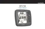
Helicopter Rotor and Engine RPM Indicator
Piston engine powered helicopters have engines directly connected to the ro-
tor (using some transmission, of course). So rotor RPM is directly related
to engine RPM. The instrument on Figure 23 gives rotor and engine RPM
expressed in percentages. The scales are set in such way that needles under
normal operation have the same indication. Any misalignment of needles can
be easily spotted giving a clear indication that something is wrong with the
transmission.
Figure 23:
The combination of rotor RPM and engine RPM. Both scales are
in percentages.
Like in the gyroplane case, the bottom window can be configured to show the
manifold pressure.
3.11.7
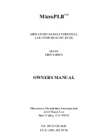
Mini Engine Monitor
The mini engine monitor window shows the most relevant engine information
in one place in the form of color bars, see Figure 24. Each bar corresponds to
one engine parameter. Green, yellow and red colors represent normal, caution
and dangerous range, respectively.
The monitor bars are grouped into temperatures, pressures, electrics and
RPMs. The temperature group includes CHT, EGT, oil and water (coolant)
temperature. The pressure group contains oil and fuel pressures. Electrical
section contains voltage and current. When monitor is shown on the naviga-
tion screen, engine RPM and rotor RPM bars are shown as well.
45
©
Kanardia
2018-2022
Содержание Nesis III
Страница 1: ...Nesis III User s Manual Kanardia d o o April 2022 Release for software version 3 9...
Страница 2: ......