KaCool D
02.02.2017
40
Installation and Connection
Control overview
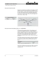
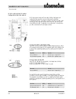
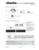
Max. 300 m
3*
3*
3*
230V / 50Hz
230V / 50Hz
230V / 50Hz
Max. 20 units
per group
3**
3**
3**
Remote control range
About 3 m
AC fans, infra-red remote control
Group formation
To form a group with up to 20 units, connect the units to each
other with a data cable as shown in the illustration opposite.
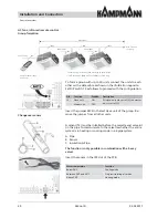
Set DIP switch 10 as follows to proceed with the con
fi
guration.
Insert the jumper MC2 in the last slave unit of the group. Re-
move the jumper from all other units.
DIP
Function
Position
Description
10
Slave unit
ON
All slave units are set to ON, the master
unit is set to OFF.
Master unit
OFF
Changeover sensor
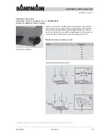
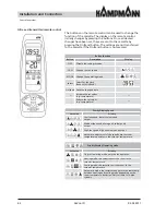
A sensor (T2) must be installed before the cassette and valve kit
on the pipe to communicate to the cassette whether the entire
system is in heating or cooling mode in a 2-pipe system.
A Pipe
B Sensor
C Insulation A Pipe
The function is only possible in combination with a 3-way
valve!
Insert the sensor in the JP2 slot of the PCB.
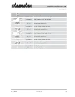
Water temperature
Function
Below 20°C
Cooling mode
Between 20°C and 30°C
Only recirculating air mode
Above 30°C
Heating mode
* Connection e.g. as NYM-J, sized according to cable length.
** CAT5 connection (AWG 23 or equivalent), linear wiring.


