Kahlenberg M-522 Скачать руководство пользователя страница 9

Kahlenberg 

Instructions, M-522, Software Rev. R., Rev. 10/7/2019 


Page 9 of 10 


In the event an external General Emergency Alarm System is used to generate the GEA code, an 

input is available on the M-522 to accept this signal which will in turn operates all lights and 

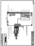
horns connected to the M-522.  See Drg. 3-6749 for connections. 


Abandon Ship Code: 


The M-522 is able to generate the Abandon Ship Code (1 second on, 1 off, 7 on, 1 off, 1 on, 1 

off, 7 on, 3 seconds off, repeating) per certain flag state requirements.  This must be started and 

stopped by an external push button (momentary or maintained, not included with M-522) that is 

constructed in accordance with requirements as stated by various flag state authorities.   This 

connection includes a .5 second delay feature before the signal will be generated, in case the 

switch is accidentally depressed.   Once started, the signal overrides all other signaling functions 

of the M-522 except the PA Interrupt, to mute the signal in the event the external Public Address 

is used.  See Drg. 3-6749 for connections. 

Sound Surveillance “Mute” Relay: 


A normally open relay is included in the M-522 that closes upon the activation of any horn 

controlled by the M-522 Control.  This is available to mute an external Sound Surveillance 

System if installed on the vessel.  See Drg. 3-6749 for connection location. 


4.)


CARE AND MAINTENANCE

 -  


The M-522 Sound and Light Control is a solid state device designed to provide many years of 

maintenance free operation.  However, in the event that a power surge takes place or 

inappropriate wiring connections are made, fuses within the unit will fail to prevent damage to 

the circuitry.  


SPARE FUSE LOCATIONS:  Spare fuses are included with the M-611 Unit and exist on the 

circuit board.   2 Amp fuses are located at F13, F14, and F15.  These are replacements for fuses 

at locations F3-F11.   500 milliamp fuses are located at F12 and F16.   These are replacements 

for fuses at locations F1 and F2. 


There are no additional user serviceable components included in the M-522.  However if any 

parts or complete circuit boards as listed on the attached Parts List drawings are required for any 

reason, please refer to the associated part number when ordering.  If the M-522 should fail to 

operate correctly for reasons other than a blown fuse as mentioned above, contact Kahlenberg 

Industries for recommended action or return to Kahlenberg for prompt analysis and repair. 


For long term storage, the M-522 should be kept in dry conditions, inside dustproof corrogated 

packaging or equivalent including a silica gel packet for absorption of humidity. 


When cleaning the membrane switch panel, we recommend the use of Windex (or equivalent) or 

a mild soap/water solution applied with a soft cotton cloth.  


Содержание M-522

Страница 1: ...operated in conjunction with external Sound Surveillance Systems and or Public Address systems Multiple M 522 units can be utilized on the vessel and will communicate with each other in cases where mu...

Страница 2: ...Terminal 33 PA Interrupt 1 Terminal 34 External Momentary Pushbutton for Automated Horn Signals 1 Terminal 29 Negative D C Connection External 24 VDC Power 1 Terminals 35 36 Additional Contact Closur...

Страница 3: ...e in conjunction with the M 522 such as external General Alarm Systems Setting SW1 Switches On the internal circuit board of the M 522 there is a switch assembly labeled SW1 Settings on this switch as...

Страница 4: ...ther or not the M 522 Controller will allow the aft and forward horn to sound simultaneously Per IMO Rules where two ship whistles are installed a distance greater than 100M apart they must not be sou...

Страница 5: ...uld be connected per Drg 3 6749 utilizing shielded cables and wire gauge per electrical requirements as given below Power Source Required 100 240 Volt A C 50 60 Hz 1 Ph AND OR 8 30 Volts D C Electrica...

Страница 6: ...s IMO COLREGS RULE 35 These automated signals are controlled by the row of buttons directly beneath the ships graphic on the faceplate as shown below Automatic On Off The Automatic On Off button start...

Страница 7: ...ows per IMO COLREGS RULE 35 One Prolonged Signal______________________Making Way through Water Underway Two Prolonged Signals____ Underway But Stopped and making no way through the water One Prolonged...

Страница 8: ...Drg 3 6749 for connection locations These external push buttons make contact for 24 Volts to the M 522 input from a remote power source An optional 100 240 VAC to 24 VDC power supply model M 800 is a...

Страница 9: ...f installed on the vessel See Drg 3 6749 for connection location 4 CARE AND MAINTENANCE The M 522 Sound and Light Control is a solid state device designed to provide many years of maintenance free ope...

Страница 10: ...e 10 of 10 5 DRAWING REFERENCES Outline Dimensions 3 6728 Parts List 3 6729 Wiring Diagrams 3 6749 General or as Specified by Contract Kahlenberg Industries Inc 1700 12th St P O Box 358 Two Rivers WI...

Страница 11: ......

Страница 12: ......

Страница 13: ......

Страница 14: ...n Active Auto Code Red LED Timer 120 Seconds Timer 90 Seconds Timer 60 Seconds Timer 40 Seconds Code 1 LED Byte 3 Bit 0 Bit 1 Bit 2 Bit 3 Bit 4 Bit 5 Bit 6 Bit 7 Code 2 LED Code 3 LED Code 4 LED Code...

Страница 15: ...tion Message Number Time Offset ms Bus Type ID hex Reserved Data Length Code Data Bytes hex FWD HORN 171 5383 214 1 Rx 00000002 00 8 02 00 00 00 00 00 00 00 172 5408 895 1 Rx 00000001 00 8 01 00 08 00...

Отзывы: