Kahlenberg M-522 Скачать руководство пользователя страница 15

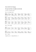
Message from slave (or alternate device) 

CAN-ID – Unit Address (0x002 to 0x004) 

Byte 0 – Unit Address (0x02 to 0x04) 

Byte 1 

Bit 0 

Bit 1 

Bit 2 

Bit 3 

Bit 4 

Bit 5 

Bit 6 

Bit 7 

Horn 
Select 

Morse 
Select 

Aft Horn 
Key 

Gong Key 

Bell Key 

Morse 
Light Key 

FWD 
Horn Key 

Auto Code 
Key 

Byte 2 

Bit 0 

Bit 1 

Bit 2 

Bit 3 

Bit 4 

Bit 5 

Bit 6 

Bit 7 

Timer 
Select 

Code 1 
Key 

Code 2 
Key 

Code 3 
Key 

Code 4 
Key 

Code 5 
Key 

At Anchor 
Key 

Aground 
Key 

Byte 3 

Bit 0 

Bit 1 

Bit 2 

Bit 3 

Bit 4 

Bit 5 

Bit 6 

Bit 7 

Alt Stbd 
Key 

Alt Port 
Key 

Astern 
Key 

Danger 
Key 

120VAC 
Power Fail 

Remote 
Start PB 

At Will 
PB 

Morse 
Light PB 

Byte 4 

Bit 0 

Bit 1 

Bit 2 

Bit 3 

Bit 4 

Bit 5 

Bit 6 

Bit 7 

PA Int PB 

GEA PB 

Abandon 
Ship PB 

Unused 

Unused 

Unused 

Unused 

Unused 

Key Pressed = 1, Key Released = 0 

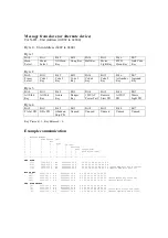
Example communication 

;   Message Number 
;   | 

 Time Offset (ms) 

;   | 

 | 

 Bus 

;   | 

 | 

 | 

 Type 

;   | 

 | 

 | 

 | 

 ID (hex) 

;   | 

 | 

 | 

 | 

 | 

 Reserved 

;   | 

 | 

 | 

 | 

 | 

 |   Data Length Code 

;   | 

 | 

 | 

 | 

 | 

 |   | 

 Data Bytes (hex) ... 

;   | 

 | 

 | 

 | 

 | 

 |   | 

 | 

;   | 

 | 

 | 

 | 

 | 

 |   | 

 | 

;---+-- ------+------ +- --+-- ----+--- +- -+-- -+ -- -- -- -- -- -- -- 

FWD HORN 

171)

5383.214 1  Rx

 00000002 00 8 

 02 00 00 00 00 00 00 00 

172)

5408.895 1  Rx

 00000001 00 8 

 01 00 08 00 00 7B 80 2E 

173)

5446.479 1  Rx

 00000002 00 8 

 02 40 00 00 00 00 00 00 (Slave FWD Horn Key Pressed) 

174)

5450.233 1  Rx

 00000001 00 8 

 01 00 0A 00 00 7B 80 2E (Master FWD Horn Active) 

MORSE KEY 

102)

3206.715 1  Rx

 00000002 00 8 

 02 00 00 00 00 00 00 00 

103)

3229.197 1  Rx

 00000001 00 8 

 01 00 08 00 00 7B 81 31 

104)

3269.937 1  Rx

 00000002 00 8 

 02 20 00 00 00 00 00 00 (Slave Morse Key Pressed) 

105)

3292.291 1  Rx

 00000001 00 8 

 01 80 08 00 00 7B 81 31 (Master Morse Active) 

FWD HORN SELECT 

73)

2335.323 1  Rx

 00000002 00 8 

 02 00 00 00 00 00 00 00  

74)

2335.920 1  Rx

 00000001 00 8 

 01 00 08 00 00 7B 81 31  

75)

2337.157 1  Rx

 00000002 00 8 

 02 01 00 00 00 00 00 00 (Slave Horn Select Pressed) 

76)

2399.100 1  Rx

 00000001 00 8 

 01 00 09 00 00 7B 81 31 (Master FWD Horn LED Active) 

Содержание M-522

Страница 1: ...operated in conjunction with external Sound Surveillance Systems and or Public Address systems Multiple M 522 units can be utilized on the vessel and will communicate with each other in cases where mu...

Страница 2: ...Terminal 33 PA Interrupt 1 Terminal 34 External Momentary Pushbutton for Automated Horn Signals 1 Terminal 29 Negative D C Connection External 24 VDC Power 1 Terminals 35 36 Additional Contact Closur...

Страница 3: ...e in conjunction with the M 522 such as external General Alarm Systems Setting SW1 Switches On the internal circuit board of the M 522 there is a switch assembly labeled SW1 Settings on this switch as...

Страница 4: ...ther or not the M 522 Controller will allow the aft and forward horn to sound simultaneously Per IMO Rules where two ship whistles are installed a distance greater than 100M apart they must not be sou...

Страница 5: ...uld be connected per Drg 3 6749 utilizing shielded cables and wire gauge per electrical requirements as given below Power Source Required 100 240 Volt A C 50 60 Hz 1 Ph AND OR 8 30 Volts D C Electrica...

Страница 6: ...s IMO COLREGS RULE 35 These automated signals are controlled by the row of buttons directly beneath the ships graphic on the faceplate as shown below Automatic On Off The Automatic On Off button start...

Страница 7: ...ows per IMO COLREGS RULE 35 One Prolonged Signal______________________Making Way through Water Underway Two Prolonged Signals____ Underway But Stopped and making no way through the water One Prolonged...

Страница 8: ...Drg 3 6749 for connection locations These external push buttons make contact for 24 Volts to the M 522 input from a remote power source An optional 100 240 VAC to 24 VDC power supply model M 800 is a...

Страница 9: ...f installed on the vessel See Drg 3 6749 for connection location 4 CARE AND MAINTENANCE The M 522 Sound and Light Control is a solid state device designed to provide many years of maintenance free ope...

Страница 10: ...e 10 of 10 5 DRAWING REFERENCES Outline Dimensions 3 6728 Parts List 3 6729 Wiring Diagrams 3 6749 General or as Specified by Contract Kahlenberg Industries Inc 1700 12th St P O Box 358 Two Rivers WI...

Страница 11: ......

Страница 12: ......

Страница 13: ......

Страница 14: ...n Active Auto Code Red LED Timer 120 Seconds Timer 90 Seconds Timer 60 Seconds Timer 40 Seconds Code 1 LED Byte 3 Bit 0 Bit 1 Bit 2 Bit 3 Bit 4 Bit 5 Bit 6 Bit 7 Code 2 LED Code 3 LED Code 4 LED Code...

Страница 15: ...tion Message Number Time Offset ms Bus Type ID hex Reserved Data Length Code Data Bytes hex FWD HORN 171 5383 214 1 Rx 00000002 00 8 02 00 00 00 00 00 00 00 172 5408 895 1 Rx 00000001 00 8 01 00 08 00...

Отзывы: