Maintenance
10 --- 63
Carry out the test exactly as described in the SIGMA CONTROL manual.
Blowoff protection and system pressure monitoring are switched off during
the test.
The machine may only be operated with a correctly functioning pressure
relief valve.
Close the user’s shut ---off valve between the machine and the air main.
Read the blowoff pressure on the valve. (the blow ---off pressure is usually to be found
at the end of the part identification)
Observe the pressure indicator on the SIGMA controller and call up the test function.
Stop the test as soon as the pressure relief valve blows off or working pressure re-
aches 10% above the blowoff set point.
If necessary, vent the machine and replace the pressure relief valve.
Deactivate the test function.
Open the user’s shut ---off valve between the machine and the air main.
10.10
Checking the Overheating Safety Shutdown Function
The machine should shut down if the airend discharge temperature reaches 110˚ C.
A detailed description of the checking procedure is to be found in the SIGMA CONTROL
service manual.
10.11
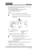
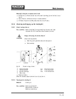
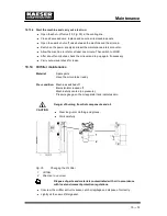
Venting the Machine Manually
Pre --- condition: Machine switched off.
Mains isolator locked off
Machine cooled down.
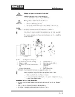
Compressed air can cause injury or death.
Compressed air and devices under pressure can injure or cause death if
the contained energy of the air is released suddenly or uncontrolled.
After shutting down the compressor and venting the oil separator tank
there is still pressure on the check valve from the air main.
Close the shut ---off valve provided by the user to isolate the machine
from the air main.
Vent the oil separator tank.
Vent the air aftercooler to completely depressurise the system between
the user’s shut ---off valve and the minimum pressure/check valve.
Escaping oil mist is damaging to health.
Do not direct the maintenance hose at a person while venting.
Do not inhale oil mist or vapour.
Avoid contact with skin and eyes.
WARNING
CAUTION
Содержание CSD 102
Страница 2: ......
Страница 85: ......
Страница 86: ......
Страница 87: ......
Страница 88: ......
Страница 89: ......
Страница 90: ......
Страница 94: ...Annex 13 86 13 Annex 13 1 Diagrams and Drawings 13 1 1 Pipeline and instrument flow diagram P I diagrams...
Страница 95: ......
Страница 96: ......
Страница 97: ......
Страница 98: ......
Страница 99: ......
Страница 100: ...Appendix 13 92 13 1 2 Pipeline and instrument flow diagram option C1...
Страница 101: ......
Страница 102: ......
Страница 103: ......
Страница 104: ......
Страница 105: ......
Страница 106: ...Appendix 13 98 13 1 3 Dimensional drawing 13 1 3 1 Air cooling option K1...
Страница 107: ......
Страница 108: ......
Страница 109: ...Appendix 13 101 13 1 3 2 Water cooling option K2...
Страница 110: ......
Страница 111: ......
Страница 112: ...Appendix 13 104 13 1 4 Electrical diagram...
Страница 113: ......
Страница 114: ......
Страница 115: ......
Страница 116: ......
Страница 117: ......
Страница 118: ......
Страница 119: ......
Страница 120: ......
Страница 121: ......
Страница 122: ......
Страница 123: ......
Страница 124: ......
Страница 125: ......
Страница 126: ......
Страница 127: ......
Страница 128: ......
Страница 129: ......
Страница 130: ......
Страница 131: ......
Страница 132: ......
Страница 133: ......
Страница 134: ......

