

7
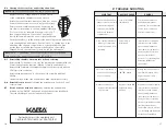
I-1
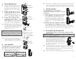
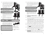
Make certain the lever catch is up as shown
(c). The lever catch should be flush around the
outer diameter of the outside driver. Make
certain the lever sleeve (f) is rotated to
properly mate with the outside lever/knob.
I-2
Insert one of the supplied keys (a) into the
outside lever/knob (b) and rotate key
counterclockwise 45 degrees.
I-3
Insert the outside lever/knob (b) until it is flush to the
outside unit assembly (levers fit closer than knobs).
Secure the outside lever/knob by rotating the key
clockwise 45 degrees to the horizontal position. Remove key.
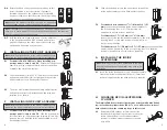
Note:
To remove the outside lever/knob from
the outside unit assembly, follow steps below.
I-4
Insert one of the supplied keys (a)
into the outside lever/knob and
rotate it counterclockwise 45
degrees. Insert the release tool (d)
into the small hole (e) under the
lever/knob as shown. Gently push
the lever catch up until it clicks.
Remove tool, then remove the
outside lever/knob.
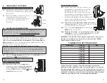
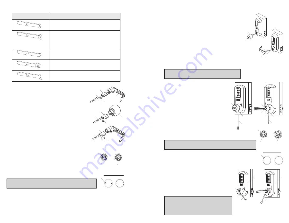
J.
INSTALLING/REMOVING
OUTSIDE LEVER/KNOB
(Interchangeable/ Removable Core Models)
Note:
Installing levers/knobs to the unit assemblies before
mounting the unit assemblies, may ease initial installation.
J-1
Make certain the lever catch is up as shown (c). The
lever catch should be flush around the entire diameter
of the outside driver. Make certain the lever sleeve (f) is
rotated to properly mate with the outside lever/knob.
J-2
Insert the outside lever/knob (a) until it
is flush to the outside unit assembly (b)
(levers fit closer than knobs). Insert the
release tool (d) (or screw- driver) into
the outside lever/knob as shown, and
slide the lever catch down until it clicks.
Note
: For all interchangeable/removable
cores except ASSA/Medeco/Yale, proceed
to section J-3. For ASSA/Medeco/Yale
cores, skip to section J-5.
6
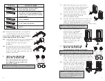
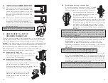
H-2
Determine the proper tailpiece (d) needed for
your KIL/KIK cylinder from the chart above.
You must use a KABA tailpiece. The K-2 tailpiece
is preassembled with the 1599 cylinder.
H-3
Assemble the required tailpiece (d) supplied with
your KIL/KIK cylinder. All tailpieces must be
installed vertically as shown for proper
installation.
H-4
Insert the KIL/KIK cylinder (a) into the outside
lever/knob (b) and secure it with the cylinder
retainer (c) and lever insert (e) (no insert on the
knob). The KIL/KIK cylinder should be snug and
unable to move freely.
I.
INSTALLING/REMOVING
OUTSIDE LEVER/KNOB
(Key-in-Lever/Knob Models only) (For
interchangeable and removable cores,
proceed to section J)
Note:
Installing lever/knob to the unit assemblies before
mounting the unit assemblies, may ease initial installation.
b
a
e
d
c
KIL Lever Sleeve
LH
RH
c
Correct
Position
Incorrect
Position
f
c
Correct
Position
Incorrect
Position
b
a
d
c
b
a
d
e
c
vertical
a
b
45º
b
a
IC Lever Sleeve
LH
RH
f
e
a
45º
d
d
e
a
b
b
d
d
a
a
Assa 65611, Australian: Kaba experT 107K5 &
Boyd KC286, Corbin-Russwin 2000-03, Kaba
1599, Schlage 23-001, Schlage Primus 20-760,
Kaba Peaks 1099
Medeco 20W200H1
Arrow C100, Sargent 10 LINE
Marks
Abloy 5277, Abloy 5477, Assa 65691,
Kaba 15396, Kaba Gemini 4730
KIL/KIK CYLINDER
TAILPIECE
K1
K3
K2
K4
K5
Содержание Simplex 5000 Series
Страница 12: ...19 18 Notes Notes ...


