Document Number 481.093 Rev. A - 06/04
16
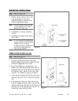
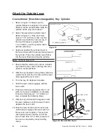
Attach the Outside Lever
Conventional (Non-Interchangeable) Key Cylinder
1. Refer to Figure 18. Make sure the
cylinder tailpiece is aligned in the same
direction as the cylinder bible. Slide the
cylinder all the way into the lever.
2. Select the appropriate cylinder insert.
Refer to Figure 19. If the door thick-
ness is 1 1/2” (38mm) or less, use the
cylinder insert with the narrow stop. If
the door thickness is greater than
1 1/2” (38mm), use the cylinder insert
with the wide stop.
3. Align and position the cylinder insert in
the lever shank with the prongs facing toward
the cylinder. Press the cylinder insert firmly
into the lever shank securing the cylinder.
Note:
Refer to Figure 20.
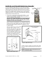
4. Ensure that the outside lock tube is oriented
such that the lever catch is facing the same
direction as the latchbolt.
5. With the key inserted in the cylinder, slide the
outside lever onto the lock tube until the lever
stops against the lever catch.
6. Turn the key 45 degrees clockwise.
7. Push the lever until it engages with the
lever catch.
8. If the door thickness is greater than 1 1/2”
(38mm), the lever installation is complete.
If the door thickness is 1 1/2” (38mm) or
less, complete the following steps.
9. With the key still turned 45 degrees, insert
the lever release tool into the lever hole to
depress the lever catch.
10. Push the lever further onto the lock tube
until the lever engages the lever catch at
the second catch position. This second
catch point ensures that the end of the
lever is less than 1/2” (13mm) away from
the door as required by many building
codes.
OUTSIDE COVER
OUTSIDE
LOCK TUBE
OUTSIDE
LEVER
LEVER RELEASE
TOOL
LEVER
CATCH
KEY
Figure 20 - Model 9000 shown
Figure 18
Figure 19
Installation
Содержание PowerLever 1550
Страница 1: ...PowerLever Door Lock Series INSTALLATION GUIDE Models 1550 4550 4560 PROX 9000 ...
Страница 4: ...SPECIFICATIONS 22 Electronic Specifications 22 Hardware Specifications 22 TROUBLESHOOTING 22 ...
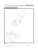
Страница 7: ...Document Number 481 093 Rev A 06 04 3 Figure 1 Parts Check PARTS CHECK Illustrated Parts Breakdown ...
Страница 28: ...Document Number 481 093 Rev A 06 04 24 ...
Страница 29: ...NOTES ...
Страница 30: ......
Страница 31: ......

